Westermo RM-115S User Manual
Page 11
115S Serial I/O Module
User Manual
man_115S_1.14.docx
Page 11
2 Installation
All connections to the module should be SELV only. Normal 110/220/240V mains
supply should not be connected to any input terminal of the module.
2.1 General installation
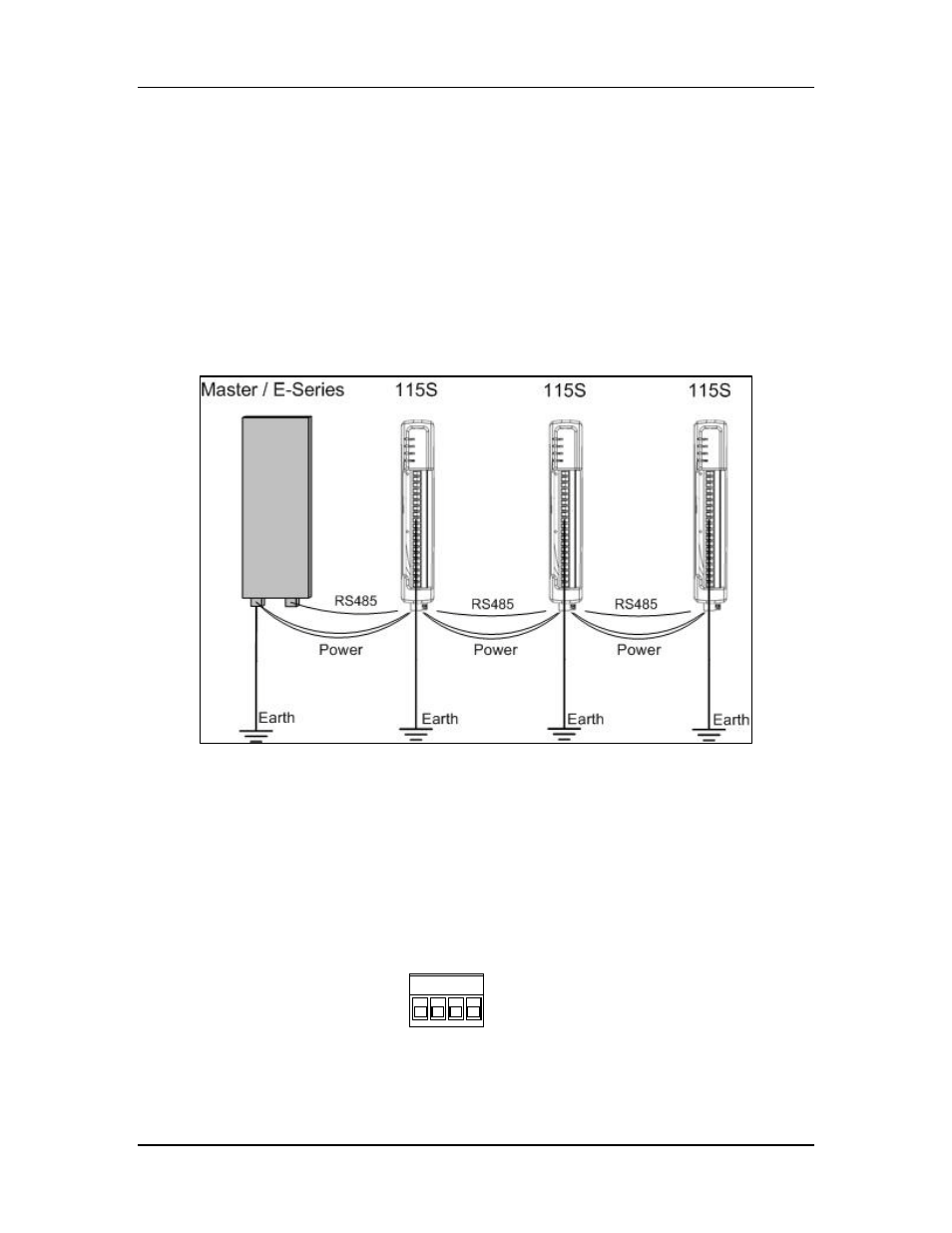
Several 115S modules may be connected to one Master / E-Series Radio via RS485
multi-drop connection as shown in Figure 2-1. Ensure there are good connections
between the 115S units and the master and a separate Earth connected to the ‘GND’
terminal on the front Terminal block of each module. 2.5 sqmm / 12 gauge earth wire is
recommended.
Figure 2-1: Several 115S units connected to a master.
2.1.1 Power Connection
The 115S modules require a 10.8-30 VDC ** power supply. This is supplied to the 4-way
connector, shown in Figure 2-2.
** Model Dependent. Check rear label for actual operating voltages
Figure 2-2: Power and RS485 connector.
Connect 10.8-30 VDC to + and earth to -. Connect RS485 to B and A.
B A
-
+