Westermo RM-115S User Manual
Page 13
115S Serial I/O Module
User Manual
man_115S_1.14.docx
Page 13
2.2 Signal Connections
All connections to the module should be SELV only. Normal 110/220/240V mains
supply should not be connected to any input terminal of the module.
2.2.1 Digital Inputs (and Pulsed Inputs)
The 115S-11 supports 16 digital signals, and the 115S-12 and 115S-13 support 8 digital
signals. Additionally, digital inputs DIO1-4 on the 115S-11 operate as pulse inputs.
Digital output signals share the same terminals as the Digital input signals, marked DIO1-
8, and DIO1-16 on the 115S-11 module.
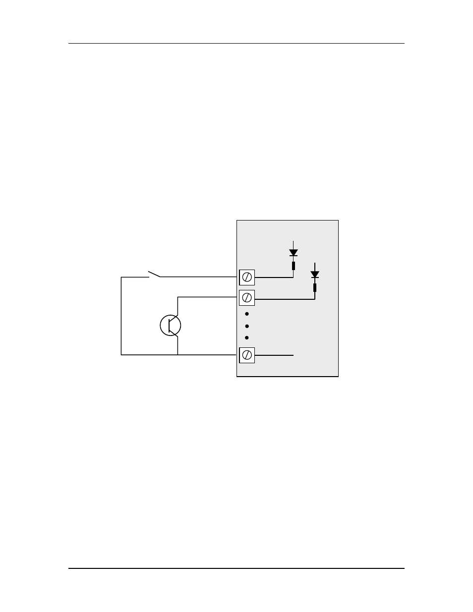
A digital input is activated by connecting to EARTH, either by voltage-free contact or by
a transistor switch. Refer to Figure 2-5:
Figure 2-5: Connection of digital inputs.
Voltage-free contact
Transistor
switch device
V+
V+
V-
DIO1
DIO2
EARTH
115S Module