2 differential current input – Westermo RM-115S User Manual
Page 35
115S Serial I/O Module
User Manual
man_115S_1.14.docx
Page 35
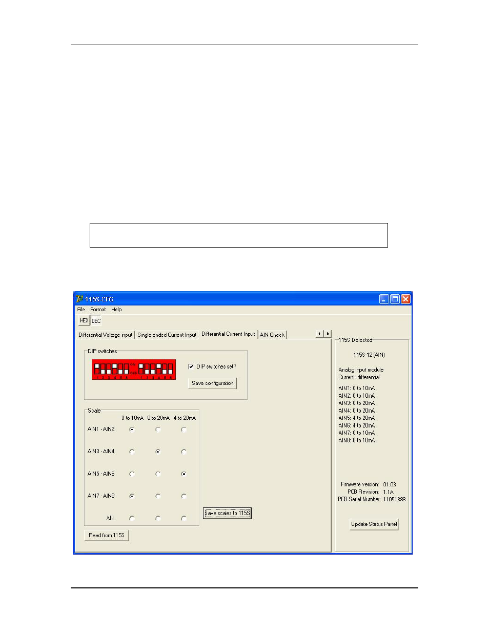
4.4.2.2 Differential current input
The 115S-12 can be configured to measure differential current. The differential pairs are:
AIN1-AIN2, AIN3-AIN4, AIN5-AIN6, and AIN7-AIN8. To use this configuration,
choose the differential current input page, as shown in Figure 4-8.
Note: If mapping Differential Analog inputs using the Elpro E-Series Configuration
software map only the Odd inputs.
E.g. AIN1 for the first Differential input, AIN3 for the second, AIN5 for the third
and AIN7 for the fourth.
If using Modbus all registers can be read but only the odd registers holds the values,
i.e. 30001 for AIN1-AIN2, 30003 for AIN3-AIN4, 30005 for AIN5- AIN6 and 30007
for AIN7-AIN8.
Remove the access panel from the front of the 115S-12 case to gain access
to the dip switches. Replace the access panel after setting the switches.
Set the switches according to the picture shown. The unit should be orientated with the
20-way connector towards you.
Figure 4-8: Setup page for differential current configuration.