Westermo RM-115S User Manual
Page 12
115S Serial I/O Module
User Manual
Page 12
June 2011
2.1.2 Address Switches
The address switches are found on the bottom panel of the module, as shown in Figure
2-3. If you are using the 115S module with other ELPRO E-Series modules (ELPRO 105
and 905- modules), the address switches must be set to “00”. This enables ELPRO
protocol mode and assigns 3 serial addresses to each module.
If you are using a Modbus Master device, ensure each 115S connected to the same
Modbus master has a unique Modbus address.
Note that the module must be reset after changing the address switches.
You can connect to an ELPRO 105U-G-MD1 or 905U-G-MD1 Module using either
MODBUS protocol or ELPRO protocol. ELPRO protocol is easier to set up, and we
recommend using this protocol for most applications.
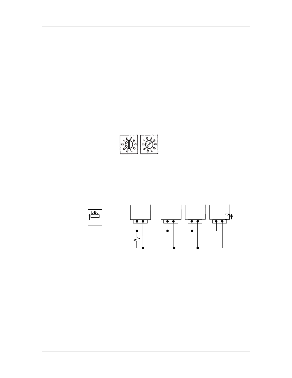
Figure 2-3: Address switches. The address shown is 01.
Connect the RS485 B and A wires to the 4-way connector shown previously in Figure
2-2. An RS485 termination switch is provided. Terminate the last 115S module in the
multi-drop setup as shown in Figure 2-4.
Figure 2-4: RS485 multi-drop connection and termination (only use external
termination for the master if it does not have internal termination).
x10
x1
ON
RS485
termination
switch.
Up = terminate
Down = unterminated
Master
115S
115S
115S
A
B
A
B
A
B
A
B
Termination
switch up
(terminated)
120
Ω