Westermo RM-115S User Manual
Page 15
Advertising
115S Serial I/O Module
User Manual
man_115S_1.14.docx
Page 15
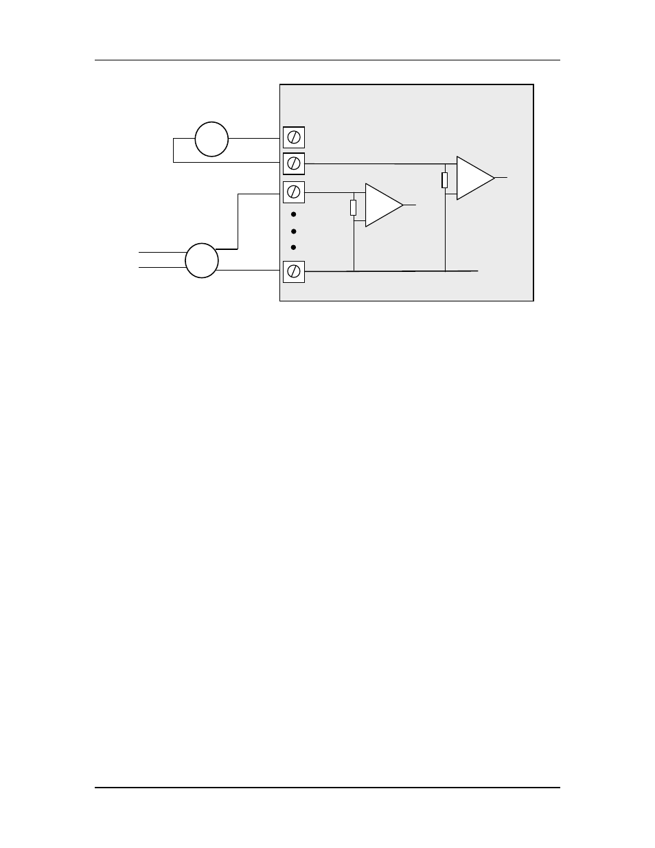
Figure 2-7: Connection for single-ended current inputs. Transducers may be
externally powered or powered by the 115S +24V loop supply.
Note:
- The module is configured at the factory for this type of input
- To change the input configuration, refer to section 4.4
WARNING !
Ensure correct DIP switch positions AND software configuration has been
completed for each analogue input BEFORE connecting external signals to the
115S-12 module.
V-
AIN1
AIN2
AGND
115S-12 Module
ALS +24V
Loop powered
sensor
Externally powered
sensor
+
-
+
-
Advertising
See also other documents in the category Westermo Equipment:
- TR-36B (88 pages)
- TD-36 (44 pages)
- TR-36 (36 pages)
- TR-36B (20 pages)
- IDW-90 AT (97 pages)
- GD-01 (206 pages)
- GD-01 (20 pages)
- MRI-128-F4G (169 pages)
- MRI-128-F4G (175 pages)
- GDW-11 485 (380 pages)
- GDW-11 (40 pages)
- Lynx Series (28 pages)
- ODW-720-F2 (36 pages)
- ODW-720-F1 (20 pages)
- ODW-720-F1 (24 pages)
- ODW-730-F2 (36 pages)
- ODW-730-F1 (24 pages)
- DDW-120 (24 pages)
- DDW-226-EX (24 pages)
- DDW-226-EX (24 pages)
- DR-270 (28 pages)
- DR Series (460 pages)
- ED-2x0 (20 pages)
- MRD-3x0 (199 pages)
- FD-80 (24 pages)
- FDV-206-1D-1S (24 pages)
- GD-01 US (24 pages)
- LD-01 (8 pages)
- IDW-90 (44 pages)
- Lynx-x10-F2G (16 pages)
- Lynx-x08-F2G-S2 (20 pages)
- MDI-110-F3x (16 pages)
- MR-2x0 (28 pages)
- ODW-642 (28 pages)
- PII PoE Injector (12 pages)
- Viper Series (977 pages)
- SDI-5xx (12 pages)
- RFI-xx (32 pages)
- SDI-8xx (16 pages)
- RFIR-xxx (24 pages)
- TD-29 (16 pages)
- SDW-5xx (24 pages)
- TD-23 (24 pages)
- TD-29P (16 pages)
- Viper 408 (20 pages)