3 floating differential voltage inputs, 4 single-ended voltage input – Westermo RM-115S User Manual
Page 17
115S Serial I/O Module
User Manual
man_115S_1.14.docx
Page 17
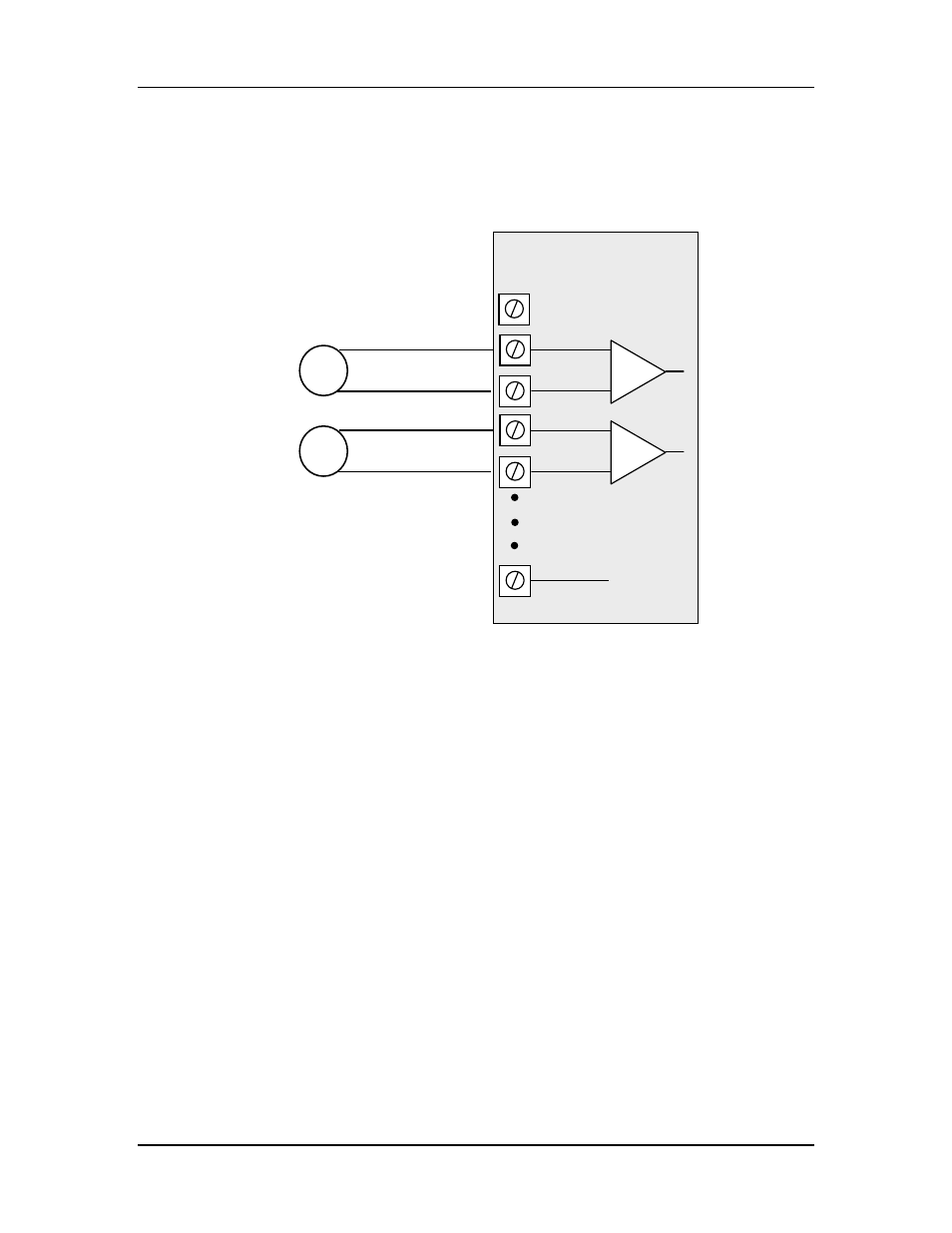
2.2.3.3 Floating Differential Voltage Inputs
Differential voltage inputs allow a voltage to be measured when it cannot be referenced
to earth or ground. The diagram in Figure 2-9 shows how to connect differential voltage
inputs. The module has a 27V common mode input range.
Figure 2-9: Connection for differential voltage input mode.
Note:
- The module configuration needs to be changed for this type of input
- To change the input configuration, refer to section 4.4
WARNING !
Ensure correct DIP switch positions AND software configuration has been
completed for each analogue input BEFORE connecting external signals to the
115S-12 module.
2.2.3.4 Single-ended Voltage Input
Single-ended voltage inputs allow twice as many inputs as differential mode. This mode
is useful when one end of the input voltage can be connected to the ground of the 115S
module. Figure 2-10 shows connections for single-ended voltage input.
V-
AIN3
AIN4
AGND
115S-12 Module
ALS +24V
Sensors with
voltage signals
AIN1
AIN2
+
-
+
-