Westermo RM-115S User Manual
Page 39
115S Serial I/O Module
User Manual
man_115S_1.14.docx
Page 39
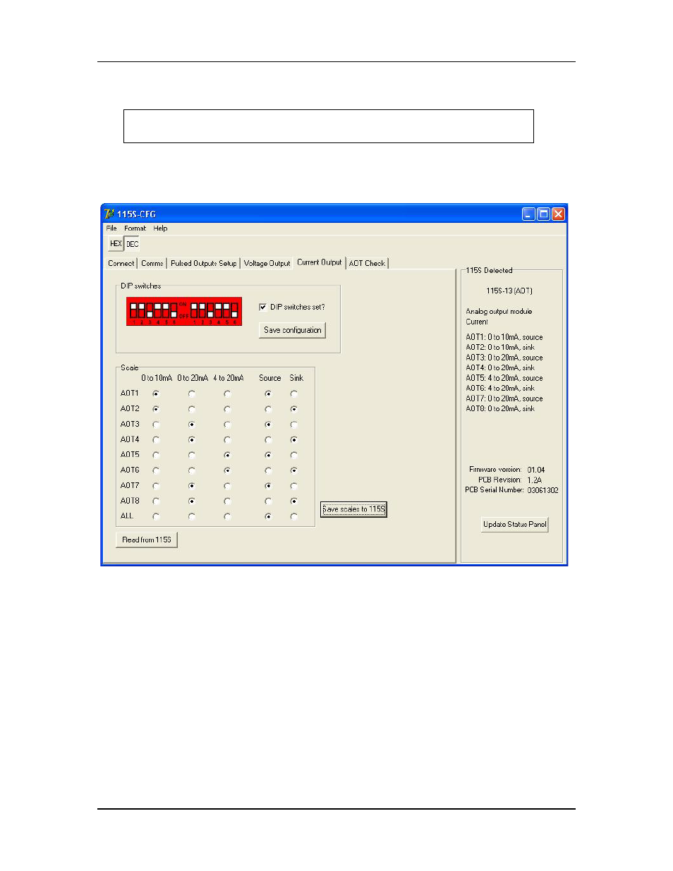
To configure the 115S-13 for current output, select the page as shown in Figure 4-10.
Remove the access panel from the front of the 115S-12 case to gain access
to the dip switches. Replace the access panel after setting the switches.
Set the switches according to the picture shown. The unit should be orientated with the
20-way connector towards you.
Figure 4-10: Current output setup page.
Once the dip switches on the unit are set, tick the checkbox on the form, and click Save
configuration. Check the 115S Detected panel to ensure that the analog mode has been
updated (to Current).
Clicking Read from 115S will read the scales out of the unit (if any) and display them in
the scales grid. Note that the dip switches should be set correctly for this result to be
relevant.
Choose the desired scale for each channel in the Scale box. Click the Save scales to 115S
button, and check that the scales are updated in the 115S Detected panel.