1 current output – Westermo RM-115S User Manual
Page 18
115S Serial I/O Module
User Manual
Page 18
June 2011
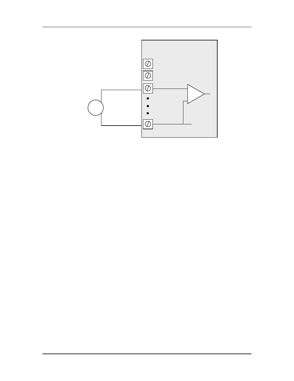
Figure 2-10: Connection for single-ended voltage input.
Note:
- The module configuration needs to be changed for this type of input
- To change the input configuration, refer to section 4.4
WARNING !
Ensure correct DIP switch positions AND software configuration has been
completed for each analogue input BEFORE connecting external signals to the
115S-12 module.
2.2.4 Analog Outputs
The 115S-13 provides eight analog outputs. These may be configured as voltage or
current outputs. The current output may be selected as “sink” or “source” current.
Refer to Section 4.5 for detail on configuring analog outputs.
2.2.4.1 Current Output
Current output mode may be configured for current source or current sink. Figure 2-11
shows the connections for current source mode. Figure 2-12 shows the connections for
current sink.
V-
AIN1
AIN2
AGND
115S-12 Module
ALS +24V
Sensor with voltage
signal
+
-