1 grounded single-ended ma inputs – Westermo RM-115S User Manual
Page 14
115S Serial I/O Module
User Manual
Page 14
June 2011
2.2.2 Digital Outputs (and Pulsed Outputs)
The 115S-11 supports up to 16 digital outputs, shared with the digital input function on
the same terminals. The 115S-12 and 115S-13 both provide 8 digital output signals.
These signals are marked DIO1-8, and DIO1-16 for the 115S-11. On all 115S modules,
DIO1-8 can also operate as pulsed outputs.
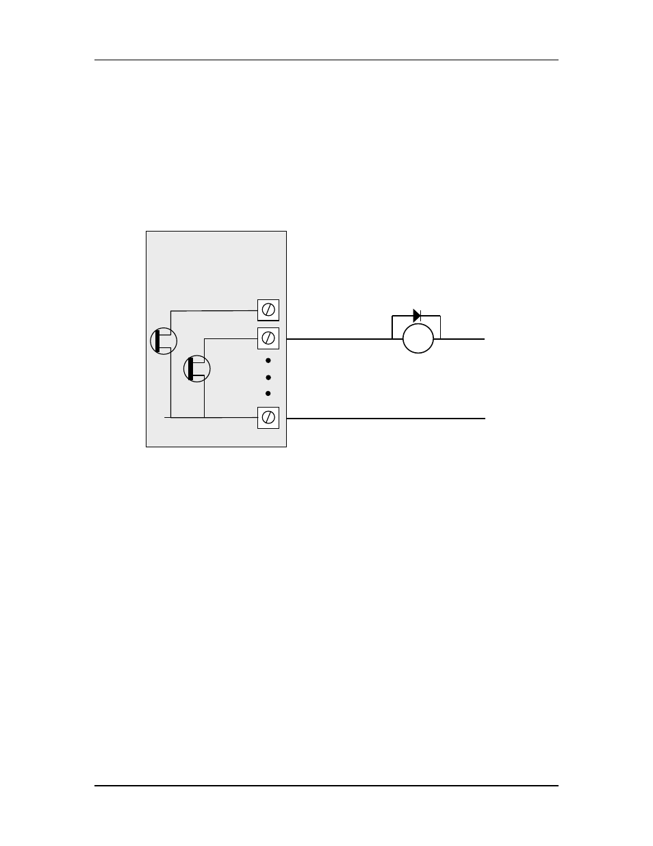
When active, digital outputs provide a transistor switch to EARTH. To connect a digital
output, refer to the diagram in Figure 2-6. A bypass diode is recommended to protect
against switching surges for inductive loads such as relay coils.
Figure 2-6: Connection of digital outputs.
Note that digital outputs will only switch DC circuits, with maximum voltage 30VDC.
2.2.3 Analog Inputs
The 115S-12 provides eight grounded single-ended or four floating differential analog
inputs. These provide measurement of voltage signals (0-10V) or current (0-20 mA)
signals. An internal 24V analog loop supply (ALS) is generated for current loops.
Refer to Section 4.4 for detail on configuring single-ended, differential, current-mode or
voltage mode inputs.
2.2.3.1 Grounded Single-Ended mA Inputs
Single-ended current inputs allow twice as many inputs as the differential mode. This
mode is useful when the sensor loop can be grounded to the 115S module. Devices may
also be powered by the 24V supplied by the 115S. Refer to Figure 2-7:
_
+
DC
Load
Max 30VDC
0.2A
V-
DIO1
DIO2
EARTH
115S Module