Westermo RM-115S User Manual
Page 41
115S Serial I/O Module
User Manual
man_115S_1.14.docx
Page 41
Test the digital outputs by setting the select-buttons to ON or OFF - this will force the
DO to the selected state.
Digital inputs are reflected in the software by blacking (ON) or greying (OFF) of the
associated label in the Digital Inputs column.
The pulsed input count values are shown, as well as the pulse rate. The rate can be
viewed in decimal or hexadecimal and represents a fraction of the maximum pulse rate,
where hex 4000 is 0% and hex C000 is 100% of the maximum pulse rate.
The pulse output count values are also shown. The pulse out target may be set by clicking
the Edit Targets button. Pulses will be produced until the count reaches the target.
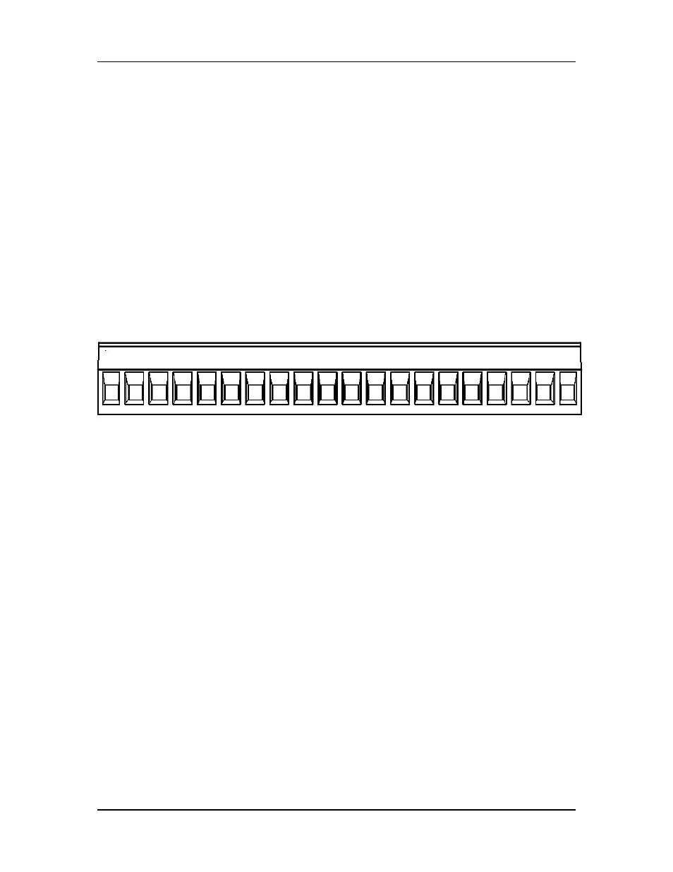
5.2 115S-12 module
The I/O terminal block for the 115S-12 is shown in Figure 5-3.
Figure 5-3: I/O terminal block for 115S-12.
Pulse outputs coincide with DIO terminals 1-8.
The operation of the 115S-12 may be confirmed using the configuration software. Start
the software as described in section 4, and choose the AIN Check page as shown in Figure
5-4.
DIO DIO DIO DIO DIO DIO DIO DIO
ALS AI+1 AI-1 AI+2 AI-2 AI+3 AI-3 AI+4 AI-4
A
ALS
1
2
3
4
5
6
7
8
Earth +24 AI 1 AI 2 AI 3 AI 4 AI 5 AI 6 AI 7 AI 8 GND +24