Westermo RM-115S User Manual
Page 48
115S Serial I/O Module
User Manual
Page 48
June 2011
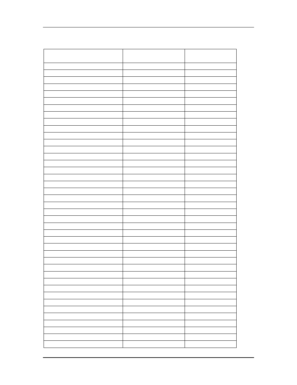
A.2. 115S-12
Data
Modbus I/O Type
Modbus
Addresses
Digital input 1
Input status
10001
Digital input 2
Input status
10002
Digital input 3
Input status
10003
Digital input 4
Input status
10004
Digital input 5
Input status
10005
Digital input 6
Input status
10006
Digital input 7
Input status
10007
Digital input 8
Input status
10008
Digital output 1
Coil status
00001
Digital output 2
Coil status
00002
Digital output 3
Coil status
00003
Digital output 4
Coil status
00004
Digital output 5
Coil status
00005
Digital output 6
Coil status
00006
Digital output 7
Coil status
00007
Digital output 8
Coil status
00008
Pulse output count 1
Input registers
30009
Pulse output count 2
Input registers
30010
Pulse output count 3
Input registers
30011
Pulse output count 4
Input registers
30012
Pulse output count 5
Input registers
30013
Pulse output count 6
Input registers
30014
Pulse output count 7
Input registers
30015
Pulse output count 8
Input registers
30016
Pulse output target 1
Holding registers
40009
Pulse output target 2
Holding registers
40010
Pulse output target 3
Holding registers
40011
Pulse output target 4
Holding registers
40012
Pulse output target 5
Holding registers
40013
Pulse output target 6
Holding registers
40014
Pulse output target 7
Holding registers
40015
Pulse output target 8
Holding registers
40016
Modbus Output Timeout
Holding registers
40204
Pulse out update time 1
Input registers
30109
Pulse out update time 2
Input registers
30110
Pulse out update time 3
Input registers
30111
Pulse out update time 4
Input registers
30112
Pulse out update time 5
Input registers
30113
Pulse out update time 6
Input registers
30114
Pulse out update time 7
Input registers
30115
Pulse out update time 8
Input registers
30116