Mpls l3vpn configuration examples, Configuring basic mpls l3vpn, Network requirements – H3C Technologies H3C S12500-X Series Switches User Manual
Page 149
138
Task Command
Remarks
Display BGP VPNv4 route
statistics.
display bgp routing-table vpnv4 statistics
Available in any view.
Display BGP VPNv4 address
family update group information.
display bgp update-group vpnv4
[ vpn-instance vpn-instance-name ]
[ ip-address ]
Available in any view.
Display OSPF sham link
information (in standalone mode).
display ospf [ process-id ] sham-link [ area
area-id ] [ standby slot slot-number ]
Available in any view.
Display OSPF sham link
information (in IRF mode).
display ospf [ process-id ] sham-link [ area
area-id ] [ standby chassis chassis-number
slot slot-number ]
Available in any view.
MPLS L3VPN configuration examples
Configuring basic MPLS L3VPN
Network requirements
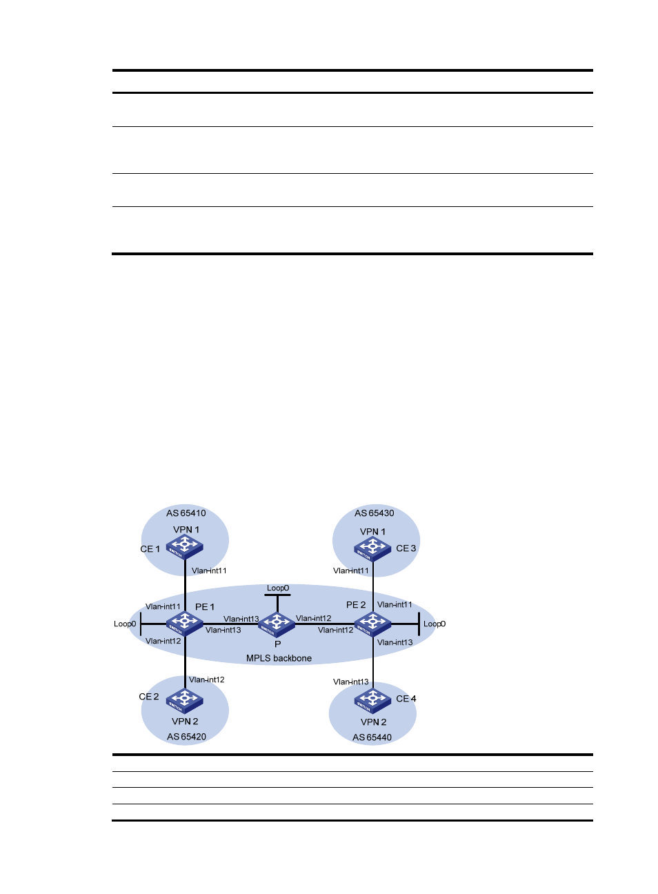
CE 1 and CE 3 belong to VPN 1. CE 2 and CE 4 belong to VPN 2.
VPN 1 uses route target attribute 111:1. VPN 2 uses route target attribute 222:2. Users of different VPNs
cannot access each other.
EBGP is used to exchange VPN routing information between CE and PE.
PEs use OSPF to communicate with each other and use MP-IBGP to exchange VPN routing information.
Figure 47 Network diagram
Device
Interface
IP address
Device
Interface
IP address
CE 1
Vlan-int11
10.1.1.1/24
P
Loop0
2.2.2.9/32
PE 1
Loop0
1.1.1.9/32
Vlan-int12 172.2.1.1/24
Vlan-int11
10.1.1.2/24
Vlan-int13
172.1.1.2/24