Establishing an mpls te tunnel with rsvp-te, Network requirements, Configuring mpls te – H3C Technologies H3C S12500-X Series Switches User Manual
Page 69: Overview, Te and mpls te
58
# Execute the display mpls lsp command or the display mpls static-cr-lsp command on each switch to
display the static CRLSP information.
[SwitchA] display mpls lsp
FEC Proto In/Out Label Interface/Out NHLFE
1.1.1.1/0/1 StaticCR -/20 Vlan1
2.1.1.2 Local -/- Vlan1
[SwitchB] display mpls lsp
FEC Proto In/Out Label Interface/Out NHLFE
- StaticCR 20/30 Vlan2
3.2.1.2 Local -/- Vlan2
[SwitchC] display mpls lsp
FEC Proto In/Out Label Interface/Out NHLFE
- StaticCR 30/- -
[SwitchA] display mpls static-cr-lsp
Name LSR Type In/Out Label Out Interface State
static-cr-lsp-1 Ingress Null/20 Vlan1 Up
[SwitchB] display mpls static-cr-lsp
Name LSR Type In/Out Label Out Interface State
static-cr-lsp-1 Transit 20/30 Vlan2 Up
[SwitchC] display mpls static-cr-lsp
Name LSR Type In/Out Label Out Interface State
static-cr-lsp1 Egress 30/Null - Up
# Execute the display ip routing-table command on Switch A. The output shows a static route entry with
interface Tunnel 0 as the egress interface.
Establishing an MPLS TE tunnel with RSVP-TE
Network requirements
Switch A, Switch B, Switch C, and Switch D run IS-IS.
Use RSVP-TE to create an MPLS TE tunnel from Switch A to Switch D.
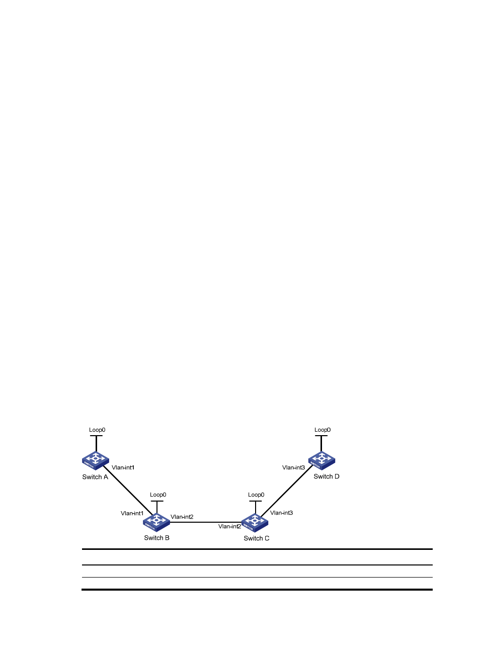
Figure 21 Network diagram
Device
Interface
IP address
Device
Interface
IP address
Switch A
Loop0
1.1.1.9/32
Switch D
Loop0
4.4.4.9/32
Vlan-int1
10.1.1.1/24
Vlan-int3
30.1.1.2/24