Configuring vpls, Overview, Basic vpls architecture – H3C Technologies H3C S12500-X Series Switches User Manual
Page 293
282
Configuring VPLS
Overview
Virtual Private LAN Service (VPLS) delivers a point-to-multipoint L2VPN service over an MPLS or IP
backbone. The provider backbone emulates a switch to connect all geographically dispersed sites of
each customer network. The backbone is transparent to the customer sites, which can communicate with
each other as if they were on the same LAN.
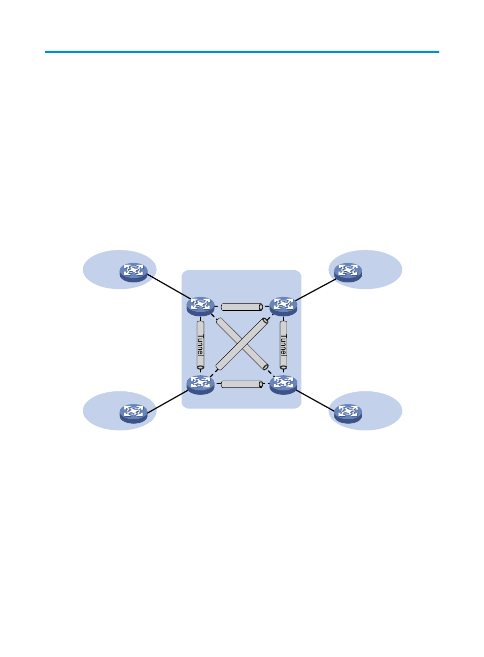
Basic VPLS architecture
Figure 74 Basic VPLS architecture
As show in
, the VPLS architecture mainly includes the following components:
•
CE—A customer edge device is directly connected to the service provider network.
•
PE—A provider edge device connects one or more CEs to the service provider network. A PE
implements VPN access by mapping and forwarding packets between private networks and public
network tunnels.
•
AC—An attachment circuit, physical or virtual, connects a CE and a PE, such as an Ethernet link or
a VLAN.
•
PW—A pseudowire is a bidirectional virtual connection between two PEs. An MPLS PW consists of
two unidirectional MPLS LSPs in opposite directions.
•
Tunnel—A tunnel can be an LSP tunnel or an MPLS TE tunnel. It carries one or more PWs over an
IP/MPLS backbone. If a PW is carried on an LSP or MPLS TE tunnel, each packet on the PW
contains two labels. The inner label is the PW label, which identifies the PW and makes sure the
VPN 1
CE 1
PE 3
PE 1
PE 2
CE 2
MPLS or IP backbone
PW
PE 4
PW
PW
PW
Site 1
VPN 2
Site 2
CE 3
VPN 1
Site 3
VPN 2
CE 4
Site 4
AC
AC
AC
AC
PW
PW
Tunnel
Tunnel
Tunnel
Tunnel