Configuration procedure – H3C Technologies H3C S12500-X Series Switches User Manual
Page 344
333
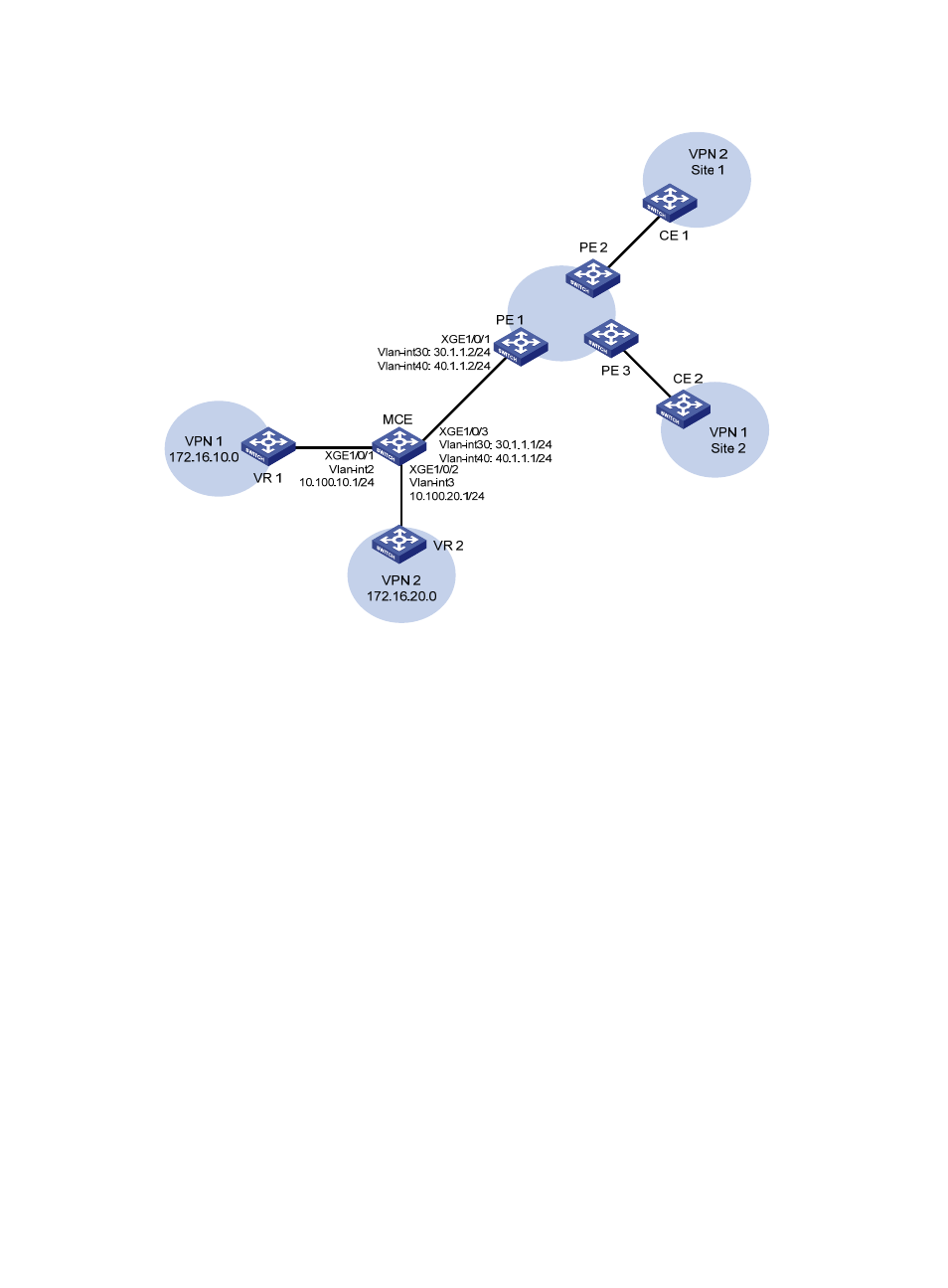
Figure 84 Network diagram
Configuration procedure
1.
Create VPN instances on the MCE and PE 1, and bind the VPN instances with VLAN interfaces.
For the configuration procedure, see "
Configure the VPN instances on the MCE and PE 1:
."
2.
Configure routing between the MCE and VPN sites:
# Enable an OSPF process on the devices in the two VPNs, and advertise the subnets. (Details not
shown.)
# Configure OSPF on the MCE, and bind OSPF process 10 with VPN instance vpn1 to learn the
routes of VPN 1.
<MCE> system-view
[MCE] ospf 10 router-id 10.10.10.1 vpn-instance vpn1
[MCE-ospf-10] area 0
[MCE-ospf-10-area-0.0.0.0] network 10.214.10.0 0.0.0.255
[MCE-ospf-10-area-0.0.0.0] quit
[MCE-ospf-10] quit
# Display the routing table of VPN 1 on the MCE.
[MCE] display ip routing-table vpn-instance vpn1
Destinations : 13 Routes : 13
Destination/Mask Proto Pre Cost NextHop Interface
0.0.0.0/32 Direct 0 0 127.0.0.1 InLoop0
10.214.10.0/24 Direct 0 0 10.214.10.3 Vlan10