Configuring a hub-spoke network, Network requirements, Configuration procedure – H3C Technologies H3C S12500-X Series Switches User Manual
Page 156
145
255.255.255.255/32 Direct 0 0 127.0.0.1 InLoop0
# CEs of the same VPN can ping each other, whereas those of different VPNs cannot. For example, CE
1 can ping CE 3 (10.3.1.1) but cannot ping CE 4 (10.4.1.1).
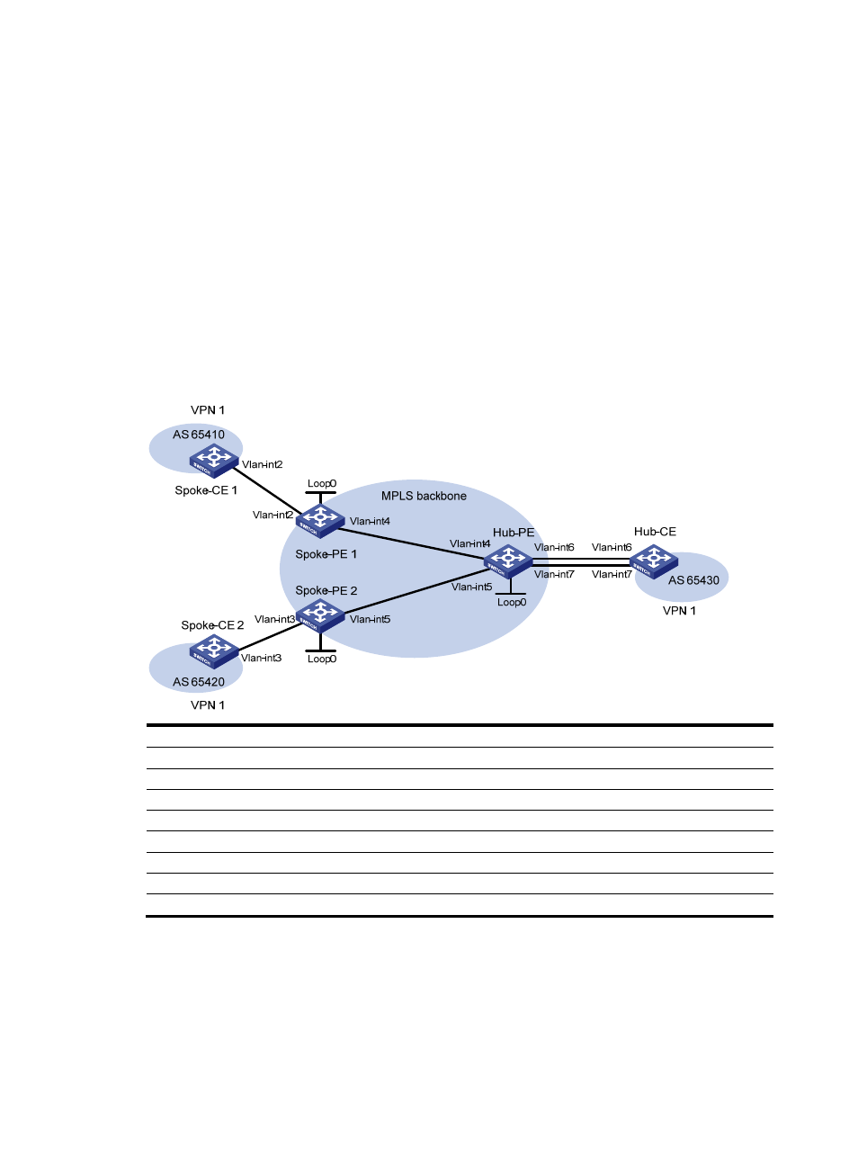
Configuring a hub-spoke network
Network requirements
The Spoke-CEs cannot communicate directly. They can communicate only through Hub-CE.
Configure EBGP between the Spoke-CEs and Spoke-PEs and between Hub-CE and Hub-PE to exchange
VPN routing information.
Configure OSPF between the Spoke-PEs and Hub-PE to implement communication between the PEs, and
configure MP-IBGP between them to exchange VPN routing information.
Figure 48 Network diagram
Device Interface IP
address
Device
Interface
IP address
Spoke-CE 1 Vlan-int2
10.1.1.1/24
Hub-CE
Vlan-int6
10.3.1.1/24
Spoke-PE 1
Loop0
1.1.1.9/32
Vlan-int7
10.4.1.1/24
Vlan-int2
10.1.1.2/24
Hub-PE
Loop0
2.2.2.9/32
Vlan-int4
172.1.1.1/24
Vlan-int4
172.1.1.2/24
Spoke-CE 2 Vlan-int3
10.2.1.1/24
Vlan-int5
172.2.1.2/24
Spoke-PE 2
Loop0
3.3.3.9/32
Vlan-int6
10.3.1.2/24
Vlan-int3
10.2.1.2/24
Vlan-int7
10.4.1.2/24
Vlan-int5
172.2.1.1/24
Configuration procedure
1.
Configure an IGP on the MPLS backbone to ensure IP connectivity within the backbone:
# Configure Spoke-PE 1.
<Spoke-PE1> system-view
[Spoke-PE1] interface loopback 0
[Spoke-PE1-LoopBack0] ip address 1.1.1.9 32