Ldp configuration examples, Ldp lsp configuration example, Network requirements – H3C Technologies H3C S12500-X Series Switches User Manual
Page 41: Configuration considerations, Configuring ldp session parameters
30
Task Command
Display LDP discovery information.
display mpls ldp discovery [ vpn-instance vpn-instance-name ]
[ interface interface-type interface-number | peer peer-lsr-id |
targeted-peer peer-lsr-id ] [ verbose ]
Display LDP FEC-label mapping
information.
display mpls ldp fec [ vpn-instance vpn-instance-name ]
[ destination-address mask-length | summary ]
Display LDP interface information.
display mpls ldp interface [ interface-type interface-number ]
Display LDP LSP information.
display mpls ldp lsp [ vpn-instance vpn-instance-name ]
[ destination-address mask-length ]
Display LDP running parameters.
display mpls ldp parameter [ vpn-instance vpn-instance-name ]
Display LDP peer and session
information.
display mpls ldp peer [ vpn-instance vpn-instance-name ]
[ peer-lsr-id ] [ verbose ]
Display LDP summary information.
display mpls ldp summary [ all | vpn-instance vpn-instance-name ]
LDP configuration examples
LDP LSP configuration example
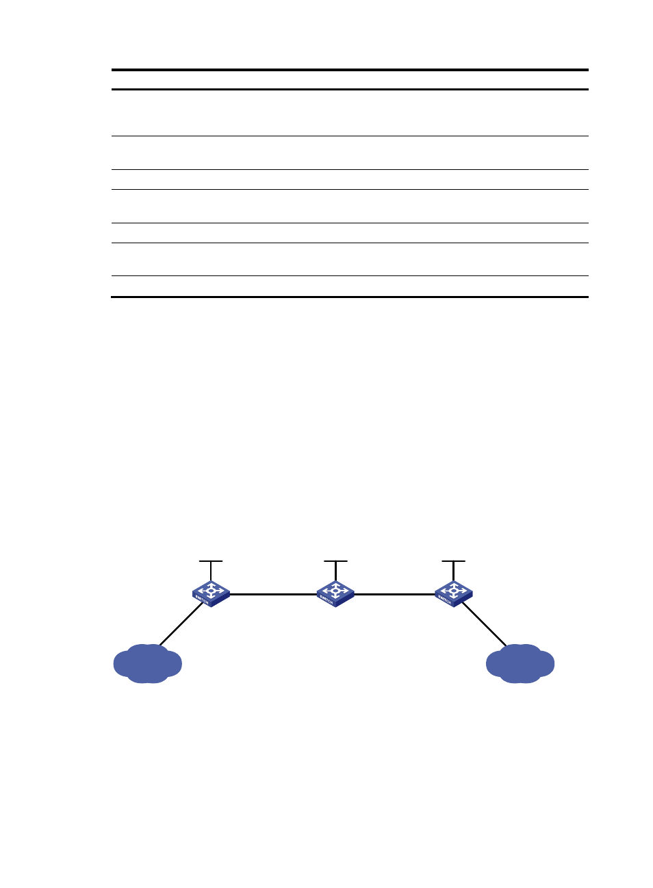
Network requirements
Switch A, Switch B, and Switch C all support MPLS.
Configure LDP to establish LSPs between Switch A and Switch C, so subnets 11.1.1.0/24 and 21.1.1.0/24
can reach each other over MPLS.
Configure LDP to establish LSPs for only destinations 1.1.1.9/32, 2.2.2.9/32, 3.3.3.9/32, 11.1.1.0/24,
and 21.1.1.0/24 on Switch A, Switch B, and Switch C.
Figure 16 Network diagram
Configuration considerations
•
LDP assigns labels according to routing information. To establish LDP LSPs, you must configure a
routing protocol to make sure the LSRs can reach each other. This example uses OSPF.
•
Enable LDP on each LSR.
•
To control the number of LSPs, configure an LSP generation policy on each LSR.
Loop0
2.2.2.9/32
Vlan-int3
20.1.1.1/24
Loop0
3.3.3.9/32
Loop0
1.1.1.9/32
Vlan-int2
10.1.1.1/24
Vlan-int2
10.1.1.2/24
Vlan-int3
20.1.1.2/24
Switch A
Switch B
Switch C
11.1.1.0/24
21.1.1.0/24
Vlan-int4
11.1.1.1/24
Vlan-int5
21.1.1.1/24