Configuration procedure, Pw redundancy – H3C Technologies H3C S12500-X Series Switches User Manual
Page 312
301
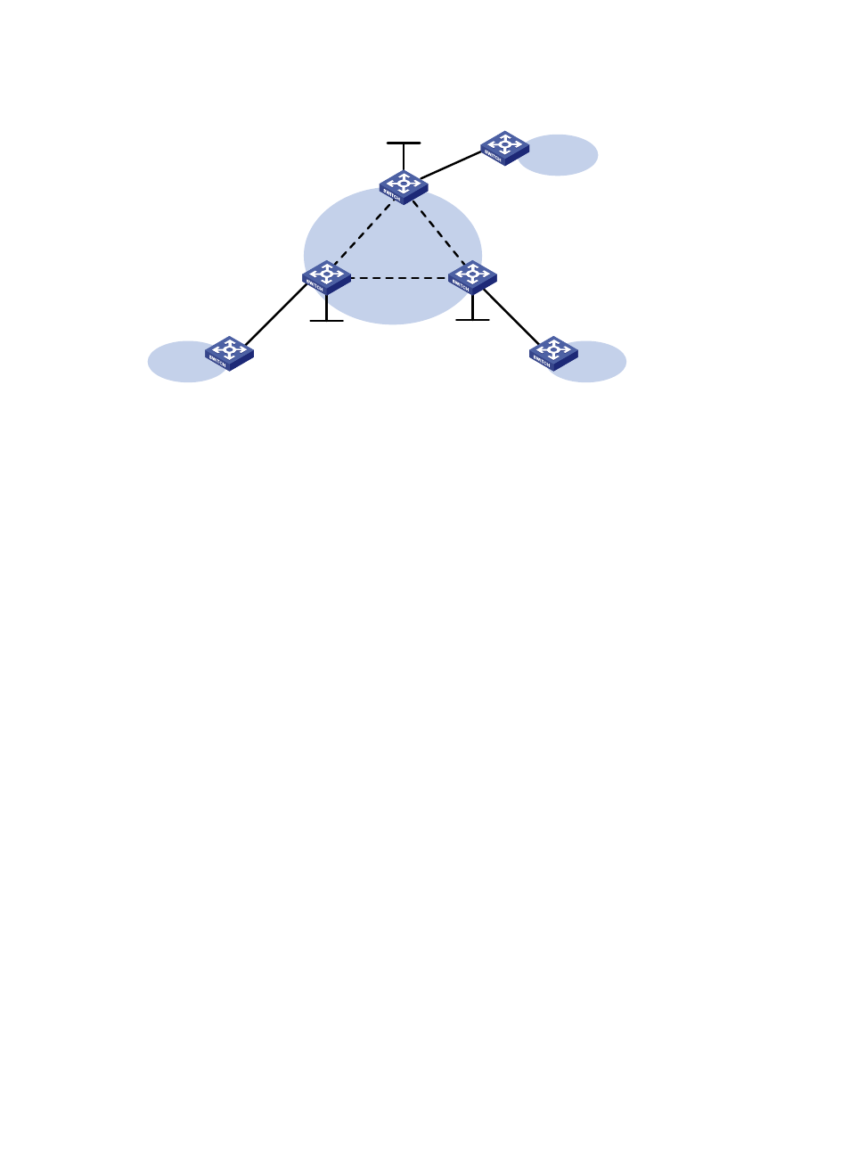
Figure 78 Network diagram
Configuration procedure
1.
Configure the IGP and public tunnels. (Details not shown.)
2.
Configure PE 1:
# Configure basic MPLS.
<PE1> system-view
[PE1] interface loopback 0
[PE1-LoopBack0] ip address 1.1.1.9 32
[PE1-LoopBack0] quit
[PE1] mpls lsr-id 1.1.1.9
[PE1] mpls ldp
[PE1-ldp] quit
# Establish IBGP connections to PE 2 and PE 3 and use BGP to advertise VPLS label block
information.
[PE1] bgp 100
[PE1-bgp] peer 2.2.2.9 as-number 100
[PE1-bgp] peer 2.2.2.9 connect-interface loopback 0
[PE1-bgp] peer 3.3.3.9 as-number 100
[PE1-bgp] peer 3.3.3.9 connect-interface loopback 0
[PE1-bgp] address-family l2vpn
[PE1-bgp-l2vpn] peer 2.2.2.9 enable
[PE1-bgp-l2vpn] peer 3.3.3.9 enable
[PE1-bgp-l2vpn] quit
[PE1-bgp] quit
# Enable L2VPN.
[PE1] l2vpn enable
# Configure the VSI aaa to use BGP to establish BGP PWs to PE 2 and PE 3.
[PE1] vsi aaa
[PE1-vsi-aaa] auto-discovery bgp
[PE1-vsi-aaa-auto] route-distinguisher 1:1
[PE1-vsi-aaa-auto] vpn-target 1:1
Loop0
1.1.1.9/32
XGE1/0/1
XGE1/0/1
CE 1
VPN 1
PE 1
PE 2
Loop0
2.2.2.9/32
CE 2
VPN 1
Loop0
3.3.3.9/32
PE 3
CE 3
VPN 1
XGE1/0/1
Vlan-int20
Vlan-int20
Vlan-int30
Vlan-int30
Vlan-int40
Vlan-int40