Configuration procedure, Configuring routing between a pe and a ce – H3C Technologies H3C S12500-X Series Switches User Manual
Page 168
157
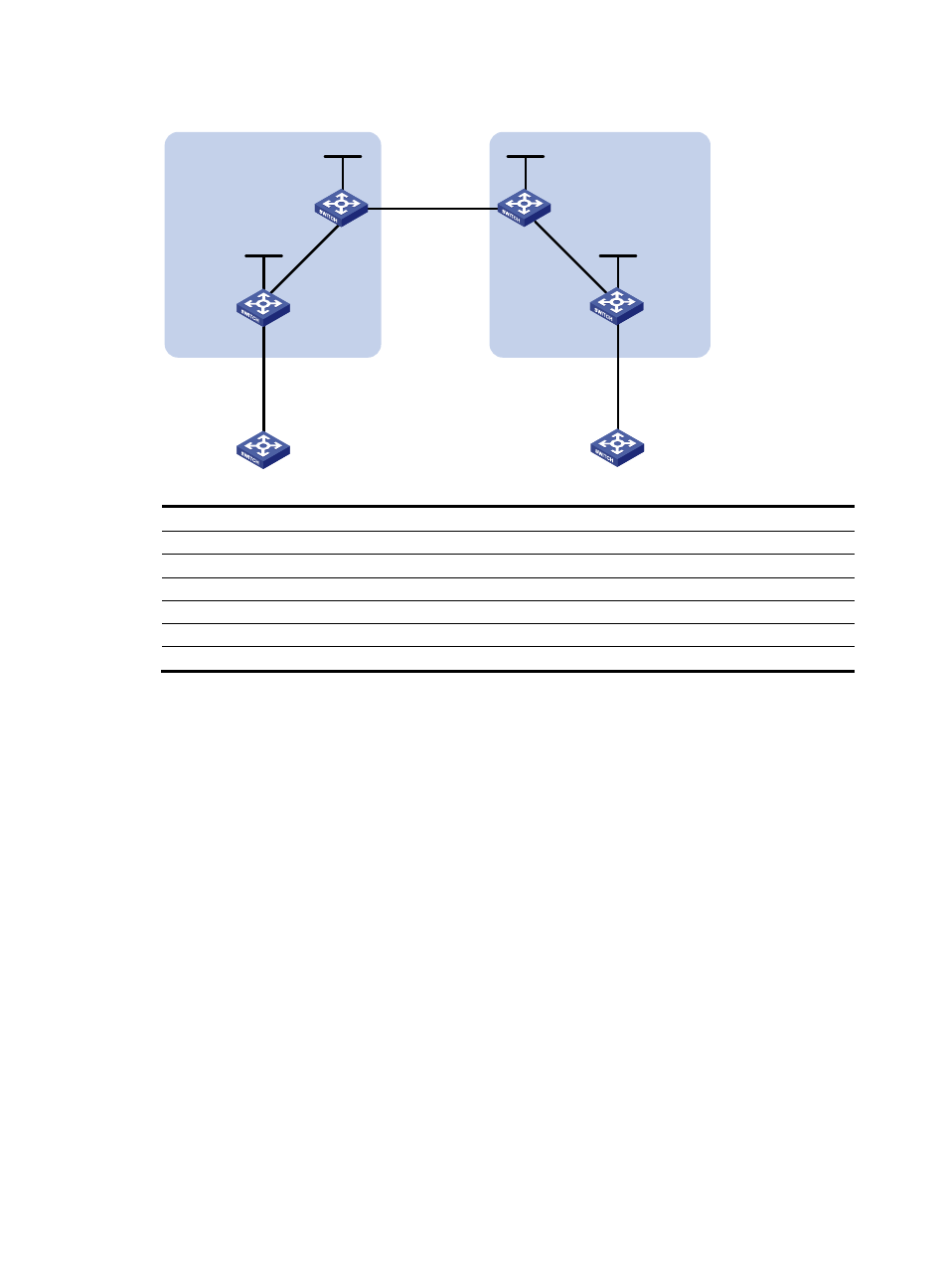
Figure 50 Network diagram
Device Interface
IP
address
Device
Interface IP
address
PE 1
Loop0
2.2.2.9/32
PE 2
Loop0 5.5.5.9/32
Vlan-int12 30.0.0.1/8
Vlan-int12 20.0.0.1/8
Vlan-int11
1.1.1.2/8
Vlan-int11 9.1.1.2/8
ASBR-PE 1
Loop0
3.3.3.9/32
ASBR-PE 2
Loop0 4.4.4.9/32
Vlan-int11 1.1.1.1/8
Vlan-int11 9.1.1.1/8
Vlan-int12
11.0.0.2/8
Vlan-int12 11.0.0.1/8
Configuration procedure
1.
Configure PE 1:
# Configure IS-IS on PE 1.
<PE1> system-view
[PE1] isis 1
[PE1-isis-1] network-entity 10.111.111.111.111.00
[PE1-isis-1] quit
# Configure the LSR ID, and enable MPLS and LDP.
[PE1] mpls lsr-id 2.2.2.9
[PE1] mpls ldp
[PE1-ldp] quit
# Configure interface VLAN-interface 11, and enable IS-IS, MPLS, and LDP on the interface.
[PE1] interface vlan-interface 11
[PE1-Vlan-interface11] ip address 1.1.1.2 255.0.0.0
[PE1-Vlan-interface11] isis enable 1
[PE1-Vlan-interface11] mpls enable
[PE1-Vlan-interface11] mpls ldp enable
[PE1-Vlan-interface11] quit
# Configure interface Loopback 0, and enable IS-IS on it.
[PE1] interface loopback 0
Loop0
Loop0
Loop0
Loop0
CE 1
CE 2
AS 65001
AS 65002
PE 1
PE 2
ASBR-PE 2
ASBR-PE 1
MPLS backbone
MPLS backbone
AS 100
AS 600
Vlan-int12
Vlan-int12
Vlan-int11
Vlan-int11
Vlan-int12
Vlan-int12
Vlan-int11
Vlan-int11
Site 1
Site 2