2 center of gravity marker on the inverter, 3 preparation for mounting, 1 drilling mounting holes in the foundation – SMA SC 500CP XT Installation User Manual
Page 16: 2 preparation for mounting on a base, Center of gravity marker on the inverter, Preparation for mounting, Drilling mounting holes in the foundation, Preparation for mounting on a base
4.2.2
Center of Gravity Marker on the Inverter
The center of gravity of the inverter is not in the middle of the device. Take this into account during transport. The center
of gravity of the inverter is marked on the packaging and on the enclosure with the center of gravity symbol.
Figure 3: Center of gravity symbol
4.2.3
Preparation for Mounting
4.2.3.1
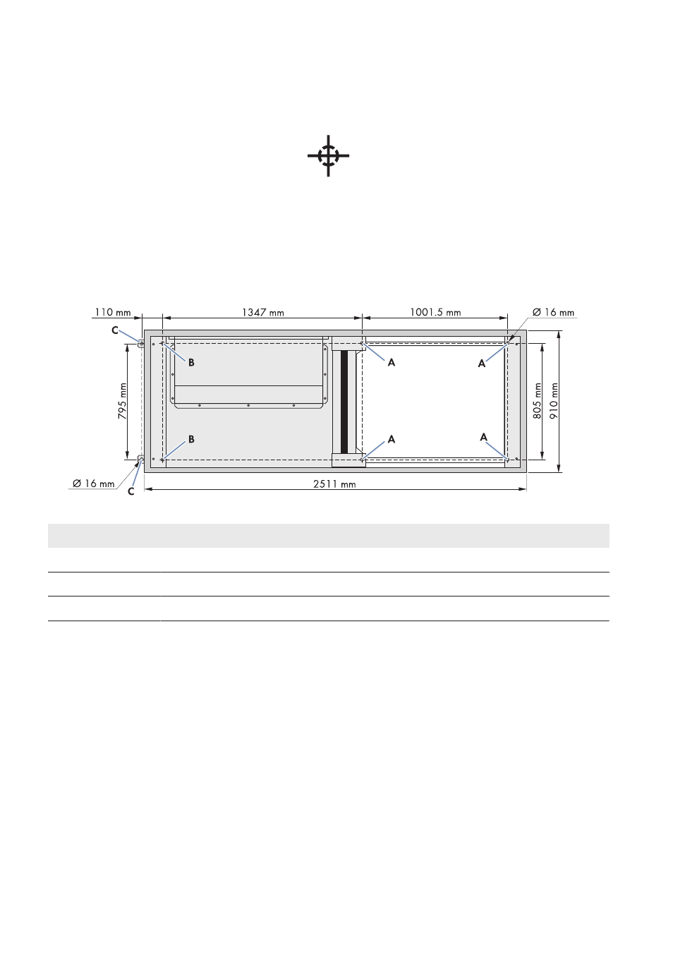
Drilling Mounting Holes in the Foundation
The inverter must be attached to the support surface by means of six bolts. Mounting holes for attaching the inverter to
the foundation or the base are located in the inverter floor.
Figure 4: Position of the mounting holes
Position
Designation
A
Mounting holes for mounting on a base or mounting surface
B
Mounting holes for mounting on a base
C
Mounting holes for mounting on a mounting surface
Additionally required material (not included in the scope of delivery):
☐ Six suitable concrete screw anchors
Procedure:
1. Mark the positions of the drill holes on the mounting surface.
2. Drill mounting holes at the marked positions.
3. Push the concrete dowels into the drill holes.
4.2.3.2
Preparation for Mounting on a Base
Requirement:
☐ The base must level off above the ground level. The base height above ground level is approx.: 150 mm.
4 Transport and Mounting
SMA Solar Technology AG
Operating Manual
SCCPXT-IA-E4-en-44
16