SMA SC 500CP XT Installation User Manual
Page 30
Procedure:
1. Disassemble the panels (see Section 7.2.1, page 40).
2. Disassemble the protective covers (see Section 7.2.2, page 41).
3. Prepare the cables for connection (see Section 7.3, page 44).
4. Clean the tin-plated contact surfaces in the connection area with the non-woven abrasive until they have a light
metallic sheen.
5. Clean all contact surfaces in the connection area using a clean cloth and ethanol cleaning agent and do not
touch the contact surfaces after cleaning.
6. Connect the cables in accordance with the circuit diagram. Only use the screws, nuts and washers included in the
scope of delivery and make sure that the screw heads always point forwards.
7. Secure the cables on the cable support rail. This will prevent the cable from being pulled out inadvertently.
8. Mount the protective covers (see Section 7.2.2, page 41).
9. Mount the panels (see Section 7.2.1, page 40).
5.6
Connecting the Cables for Communication, Control, Supply Voltage
and Monitoring
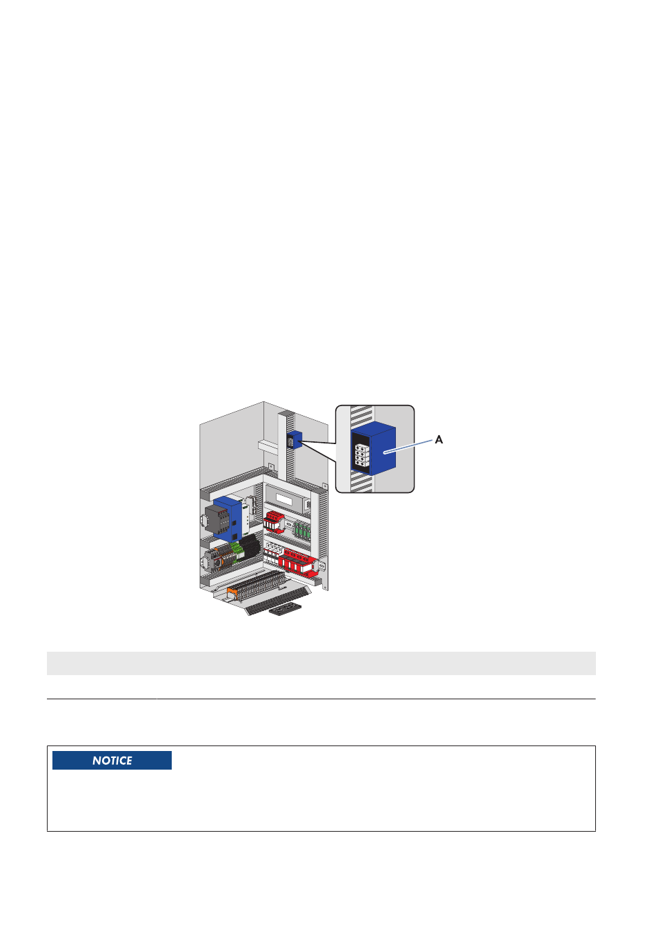
5.6.1
Connecting Optical Fibers with Subscriber Connector
Figure 10: Position of the splice box
Position
Designation
A
Splice box
Additionally required mounting material (not included in the scope of delivery):
☐ 2 subscriber connectors
Damage to optical fibers due to too tight bend radii
Excessive bending or kinking will damage the optical fibers.
• Observe the minimum permissible bend radii of the optical fibers.
5 Installation
SMA Solar Technology AG
Operating Manual
SCCPXT-IA-E4-en-44
30