3 installing the grounding, Installing the grounding – SMA SC 500CP XT Installation User Manual
Page 23
5.3
Installing the Grounding
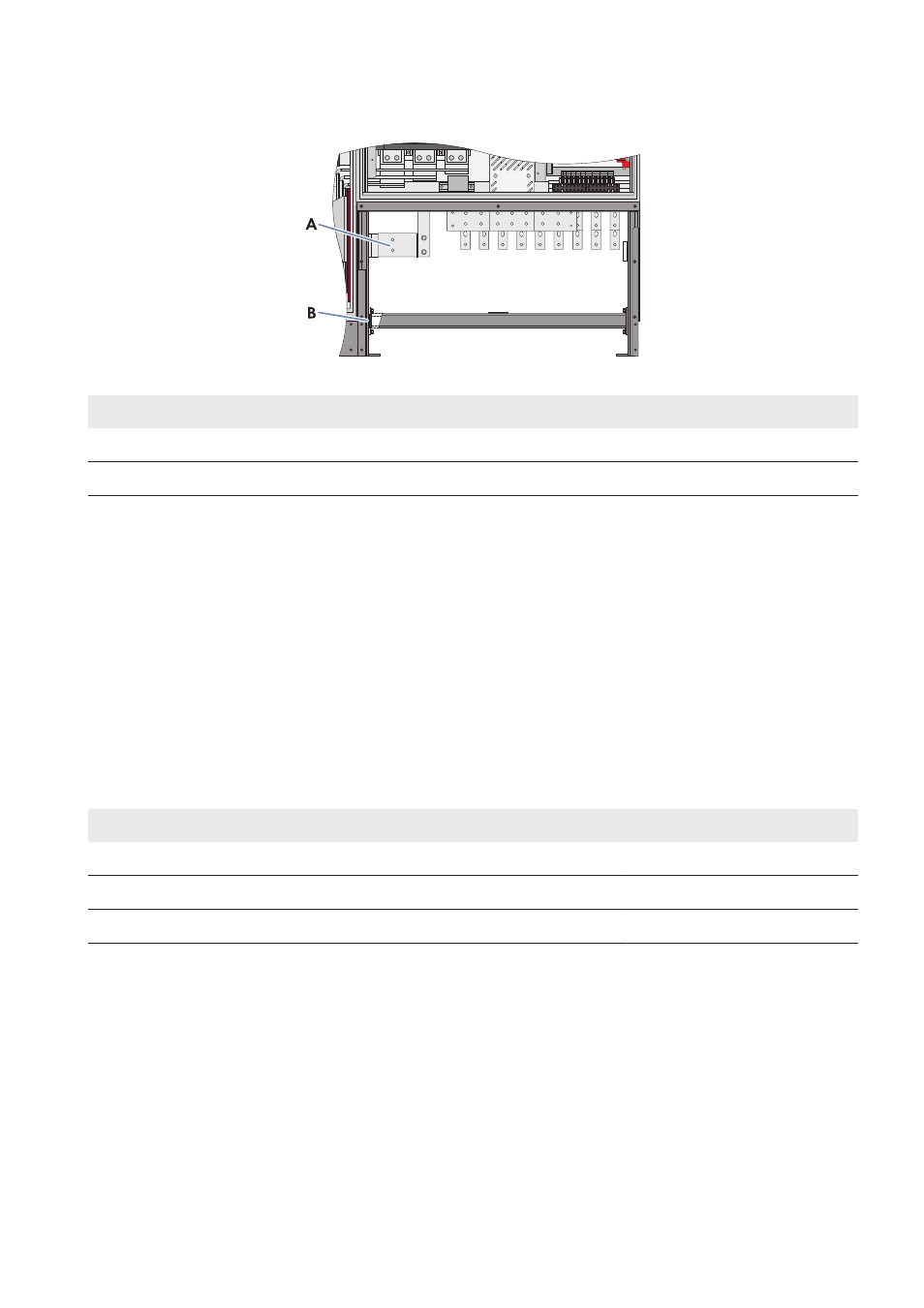
Figure 5: Position of grounding in the inverter (example)
Position
Designation
A
Grounding busbar
B
Cable support rail
Terminal lug requirements:
☐ Use tin-plated terminal lugs only.
☐ For the connection, only the supplied screws, washers and nuts must be used.
☐ The terminal lugs must be designed according to the temperature. Temperature: +95°C
☐ The width of the terminal lugs must exceed the washer diameter. Washer diameter: 32 mm. This will ensure that
the defined torques are effective over the whole surface.
Cable requirements:
☐ Do not attach more than one cable to each connection bracket.
☐ Use copper or aluminum cables only.
☐ Maximum cable cross-section: 400 mm².
Torques of the power connections:
Type of terminal lug
Torque
Tin-plated aluminum terminal lug on copper bar
37 Nm
Tin-plated copper terminal lug on copper bar
60 Nm
Tin-plated aluminum or copper terminal lug on aluminum bar
37 Nm
Additionally required mounting material (not included in the scope of delivery):
☐ Clean cloth
☐ Ethanol cleaning agent
Procedure:
1. Disassemble the panels (see Section 7.2.1, page 40).
2. Disassemble the protective covers (see Section 7.2.2, page 41).
3. Prepare the cables for connection (see Section 7.3, page 44).
4. Clean the tin-plated contact surfaces in the connection area with the non-woven abrasive until they have a light
metallic sheen.
5 Installation
SMA Solar Technology AG
Operating Manual
23
SCCPXT-IA-E4-en-44