Requirements for the foundation and cable routing – SMA SC 500CP XT Installation User Manual
Page 68
9.1.3
Requirements for the Foundation and Cable Routing
If you do not use a base from SMA Solar Technology AG, you can also position the inverter on a foundation.
The foundation must have the following properties:
☐ The foundation must be suitable for the weight of the inverter. The inverter weighs: 1,900 kg.
☐ The unevenness must be less than 0.25% (as per DIN 18202: table 3, line 4).
☐ The inclination of the foundation must be between 0.5% and 1%. This will allow rain water to drain from
underneath the inverter.
☐ The foundation must have at least the following dimensions:
Position
Designation
Width
2,600 mm
Depth
1,000 mm
☐ Cable feedthroughs must be provided in the foundation.
☐ For convenient operation and trouble-free maintenance, it is recommended to extend the inverter foundation on all
sides or to provide a level, reinforced surface around the inverter. The foundation must have the following
minimum dimensions:
Position
Designation
Width
3,400 mm
Depth
1,800 mm
☐ If the ground is to be paved up to the inverter foundation, a gap must be maintained between the foundation and
the paved area. The gap width is: 30 mm.
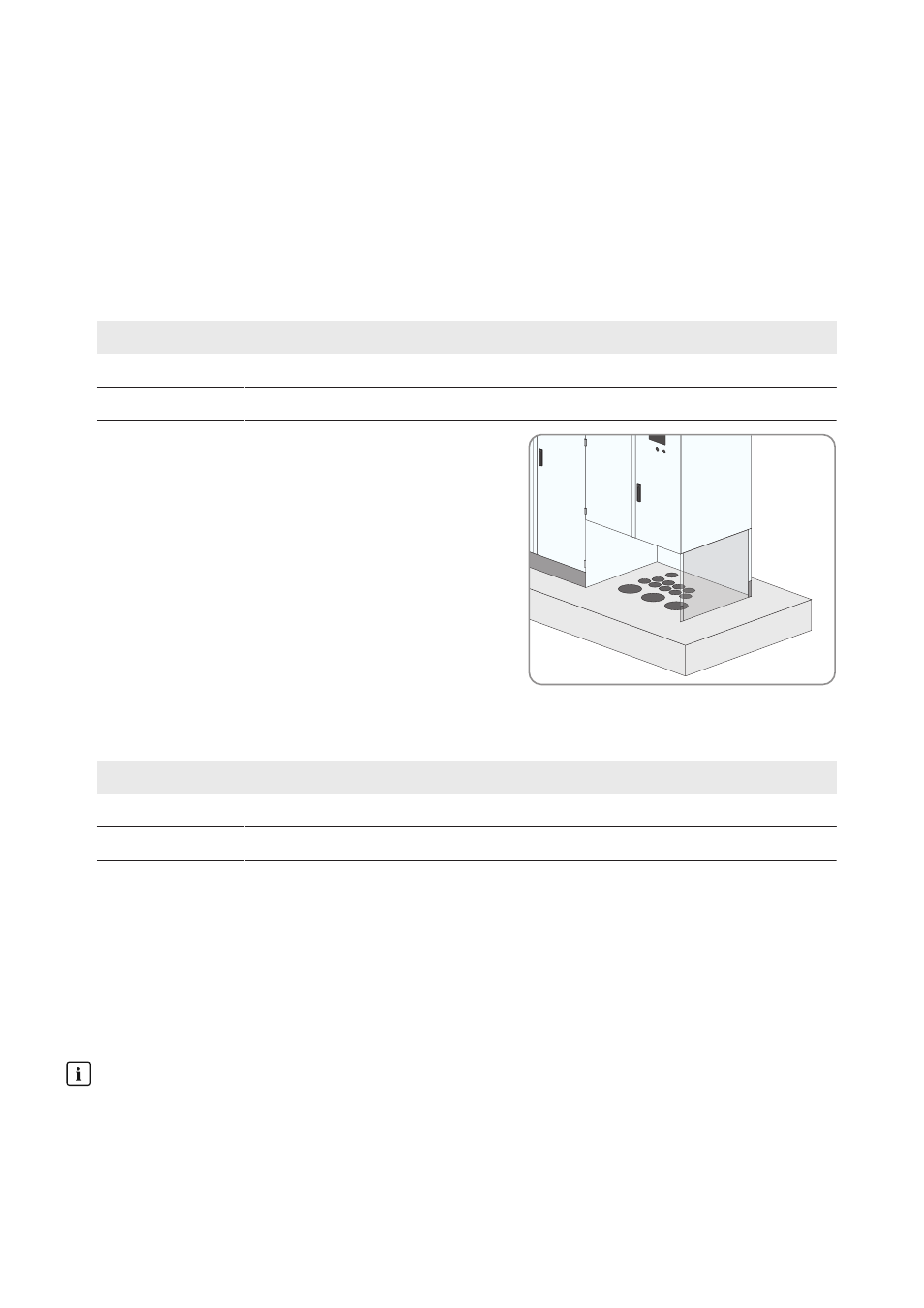
Requirements for the cable arrangement:
☐ Openings for the cables must be located in the foundation underneath the interface cabinet.
☐ Empty conduits for the cables must be laid under the foundation.
☐ Cables for communication, control and supply voltage must be separated from AC and DC cables.
☐ There must be sufficient space available to lay the cables properly.
Stage at which cables are laid
The stage at which the cables are laid must be determined individually for each system.
9 Appendix
SMA Solar Technology AG
Operating Manual
SCCPXT-IA-E4-en-44
68