SMA SC 500CP XT Installation User Manual
Page 29
Cable and cable laying requirements:
☐ The cables must be designed for the maximum voltages to ground.
For the Sunny Central 500CP XT / 630CP XT / 720CP XT / 760CP XT / 800CP XT, the maximum voltage to
ground is: ±1,450 V.
For the Sunny Central 850CP XT / 900CP XT, the maximum voltage to ground is: ±1,600 V.
☐ The cables must be designed for the maximum root-mean-square value. Maximum root-mean-square value: 800 V.
☐ Do not attach more than four cables to each AC connecting plate.
☐ Use copper or aluminum cables only.
☐ Maximum cable cross-section: 300 mm².
☐ All line conductor cables must be of the same length and must not exceed the maximum cable length. The
maximum cable length is 15 m.
☐ The AC cables must be bundled in the three-phase system.
☐ Between the MV transformer and the inverter, three separate cable routes for the AC cables must be available,
e.g. cable channels.
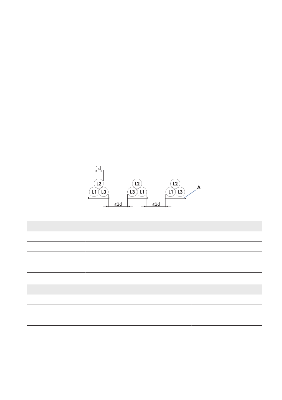
☐ A line conductor L1, L2 or L3 must be laid in each cable channel. Ensure that the distance between the cable
bundles is at least twice the diameter of a cable. This will prevent current imbalances. Furthermore, it is
recommended to execute cabling between inverter and MV transformer directly on a grounding strap. This
measure further reduces electromagnetic influences.
Figure 9: Arrangement of AC cables with three cables per line conductor (example)
Position
Designation
L1
Line conductor L1
L2
Line conductor L2
L3
Line conductor L3
A
Grounding strap
Torques of the power connections:
Type of terminal lug
Torque
Tin-plated aluminum terminal lug on copper bar
37 Nm
Tin-plated copper terminal lug on copper bar
60 Nm
Tin-plated aluminum or copper terminal lug on aluminum bar
37 Nm
Additionally required mounting material (not included in the scope of delivery):
☐ Clean cloth
☐ Ethanol cleaning agent
5 Installation
SMA Solar Technology AG
Operating Manual
29
SCCPXT-IA-E4-en-44