5 connecting the remote shutdown, 6 connecting the external setpoint specification – SMA SC 500CP-US User Manual
Page 80
12 Cable Connection of External Devices in the Interface Cabinet
SMA America, LLC
80
SCCP-US-IA-US_en-41
Installation Manual
12.5 Connecting the Remote Shutdown
The remote shutdown enables the inverter to be switched off from a control room, for example. The function of the remote
shutdown is similar to the stop position of the key switch.
Cable requirement:
☐ The cable must be shielded.
Requirements:
☐ The inverter must be disconnected (see Section 14 "Disconnecting the Inverter", page 86).
☐ The cable must be routed into the interface cabinet (see Section 12.4 "Inserting the Cables into the Interface
Procedure:
1. Dismantle the cable and strip the insulation.
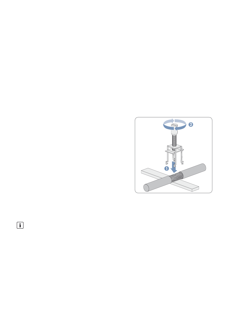
2. Remove the shield clamp from the busbar.
3. Place the cable shield on the shield bus.
4. Press the shield clamping saddle down until it clicks into place and
fasten hand-tight.
5. Connect the cable in accordance with the circuit diagram.
6. Attach the cable to the cable support rail using a cable tie. This ensures that the cable cannot be pulled out.
12.6 Connecting the External Setpoint Specification
You will find further information on how the external setpoints work in the Sunny Central user manual.
Requirements:
☐ The inverter must be disconnected (see Section 14, page 86).
☐ The cable must be routed into the interface cabinet (see Section 12.4, page 79).
Cable requirements:
☐ The cable must be shielded.
Signal transmission
External setpoints for reactive- and active power are normally specified by the grid operator and transmitted, e.g.
via a ripple control receiver. The Power Reducer Box receives the target values and sends them to the inverter via
the SC-COM. The inverter applies the specifications of the grid operator and feeds, for example, a specified reactive
power into the utility grid. Ask your grid operator which type of signal transmission is used.
If these setpoints are not transmitted via the SC-COM and Power Reducer Box, there are terminals located in the
inverter for connecting the external setpoints. The inverter processes standardized signals of 4 mA to 20 mA.