9 insulation monitoring – SMA SC 500CP-US User Manual
Page 82
12 Cable Connection of External Devices in the Interface Cabinet
SMA America, LLC
82
SCCP-US-IA-US_en-41
Installation Manual
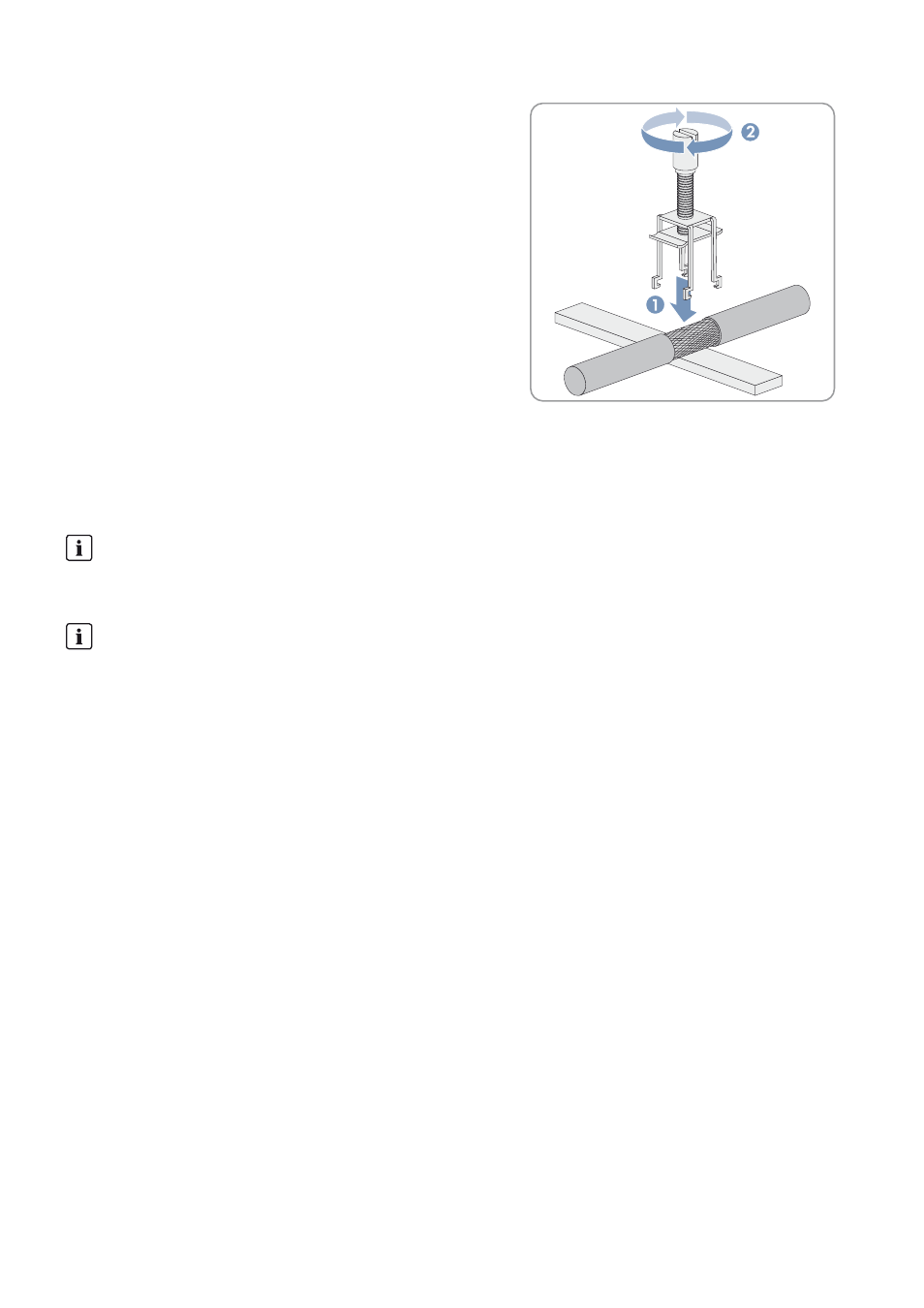
4. Press the shield clamping saddle down until it clicks into place and
fasten hand-tight.
5. Attach the cable to the cable support rail using a cable tie. This ensures that the cable cannot be pulled out.
12.8 Connecting the External Voltage Supply (Optional)
The inverter draws electric current for its internal power supply via the optional external voltage supply. You must connect
the inverter to an external auxiliary supply voltage.
Requirements:
☐ The inverter must be disconnected (see Section 14 "Disconnecting the Inverter", page 86).
☐ The cable must be routed into the interface cabinet (see Section 12.4 "Inserting the Cables into the Interface
Procedure:
1. Dismantle the cable.
2. Strip the cable insulation.
3. Connect the cable in accordance with the circuit diagram.
4. Attach the cable to the cable support rail using a cable tie. This ensures that the cable cannot be pulled out.
12.9 Insulation Monitoring
The optional insulation measuring device emits a warning if the PV field does not have sufficient insulation resistance. This
warning signal can be tapped via a potential-free relay contact (changeover contact).
Procedure:
1. Dismantle the cable and strip the insulation.
2. Connect the cable in accordance with the circuit diagram.
3. Attach the cable to the cable support rail using a cable tie. This ensures that the cable cannot be pulled out.
Circuit Breaker between the External Voltage Supply and the Inverter
A circuit breaker with a rated current of 16 A is present in the inverter.
Install a selective circuit breaker for isolating the cable to the inverter.
Maximum wire size
Use a cable with a maximum wire size of 12 AWG (4 mm
2
).