Installing the option, A1000, 5 installation procedure – Yaskawa SI-ET3 User Manual
Page 12
5 Installation Procedure
12
YASKAWA ELECTRIC SIEP C730600 62B 1000-Series Option SI-ET3 Technical Manual
Installing the Option
Remove the front covers of the drive before installing the option. Refer to the drive instruction manual for directions on
removing the front covers. Cover removal varies depending on drive size. This option can be inserted only into the
CN5-A connector located on the drive control board.
DANGER! Electrical Shock Hazard. Do not connect or disconnect wiring while the power is on. Failure to comply could result in death
or serious injury. Before installing the option, disconnect all power to the drive and wait at least the amount of time specified on the
drive front cover safety label. After all indicators are off, measure the DC bus voltage to confirm safe level, and check for unsafe
voltages before servicing. The internal capacitor remains charged after the power supply is turned off.
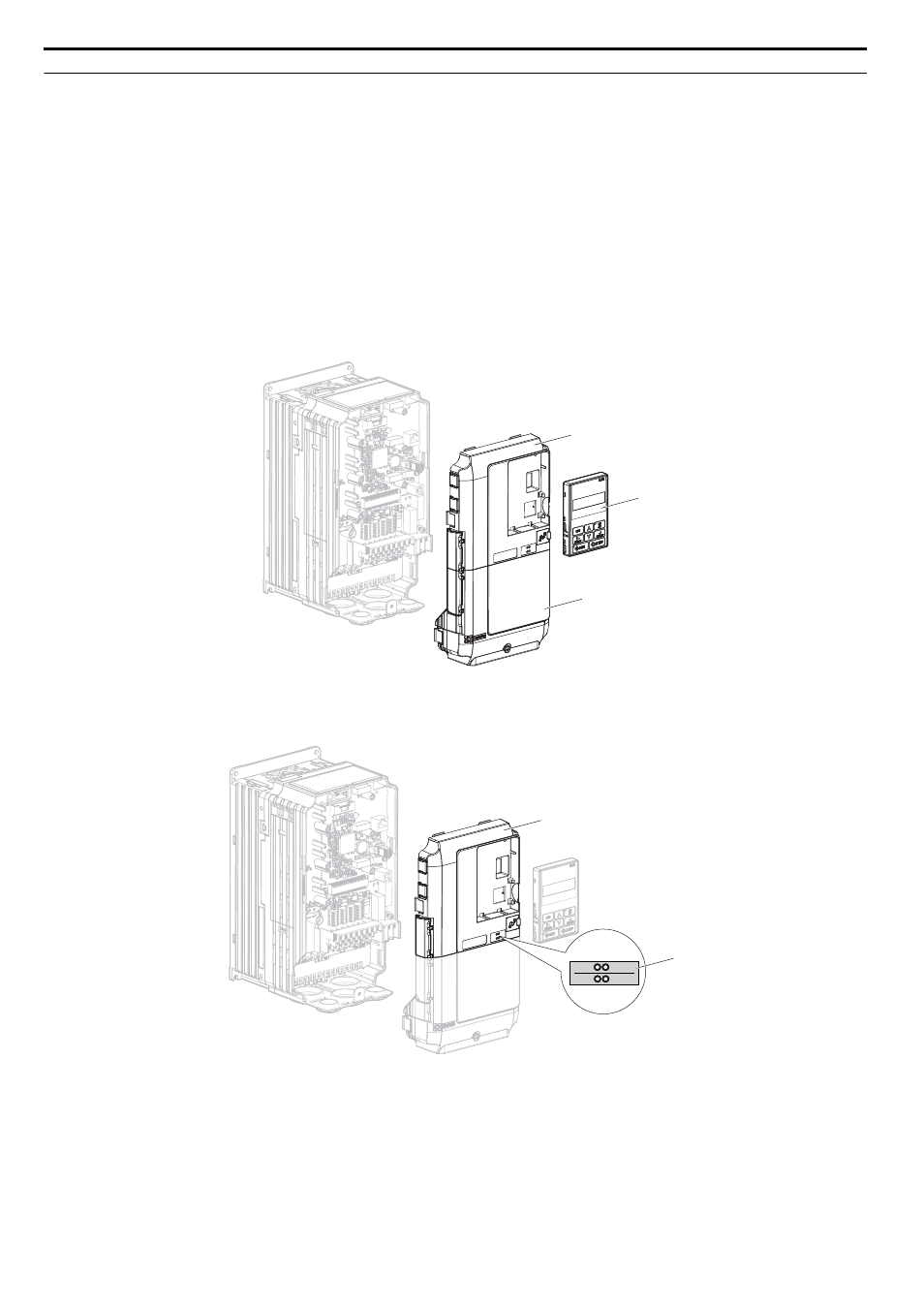
1.
Shut off power to the drive, wait the appropriate amount of time for voltage to dissipate, then remove the digital
operator (D) and front covers (C, F). Cover removal varies depending on drive size.
NOTICE: Damage to Equipment. Observe proper electrostatic discharge procedures (ESD) when handling the option, drive, and
circuit boards. Failure to comply may result in ESD damage to circuitry.
Figure 3
Figure 3 Remove the Front Covers and Digital Operator
2.
With the front covers and digital operator removed, apply the LED label (E) in the appropriate position on the
drive top front cover (C).
Figure 4
Figure 4 Apply the LED Label
C
D
F
A1000
R/E
LK1
CON
LK2
C
E
A1000