Prior to installing the option, Minor faults and alarms – Yaskawa SI-ET3 User Manual
Page 46
11 Troubleshooting
46
YASKAWA ELECTRIC SIEP C730600 62B 1000-Series Option SI-ET3 Technical Manual
Minor Faults and Alarms
Prior to Installing the Option
Prior to installing the option, wire the drive, make the necessary connections to the drive terminals, and verify that the
drive functions normally. Refer to the
for information on wiring and connecting the drive.
below lists the number of option cards that can be connected to the drive and the drive connectors for
connecting those option cards.
Table 26 Option Card Installation
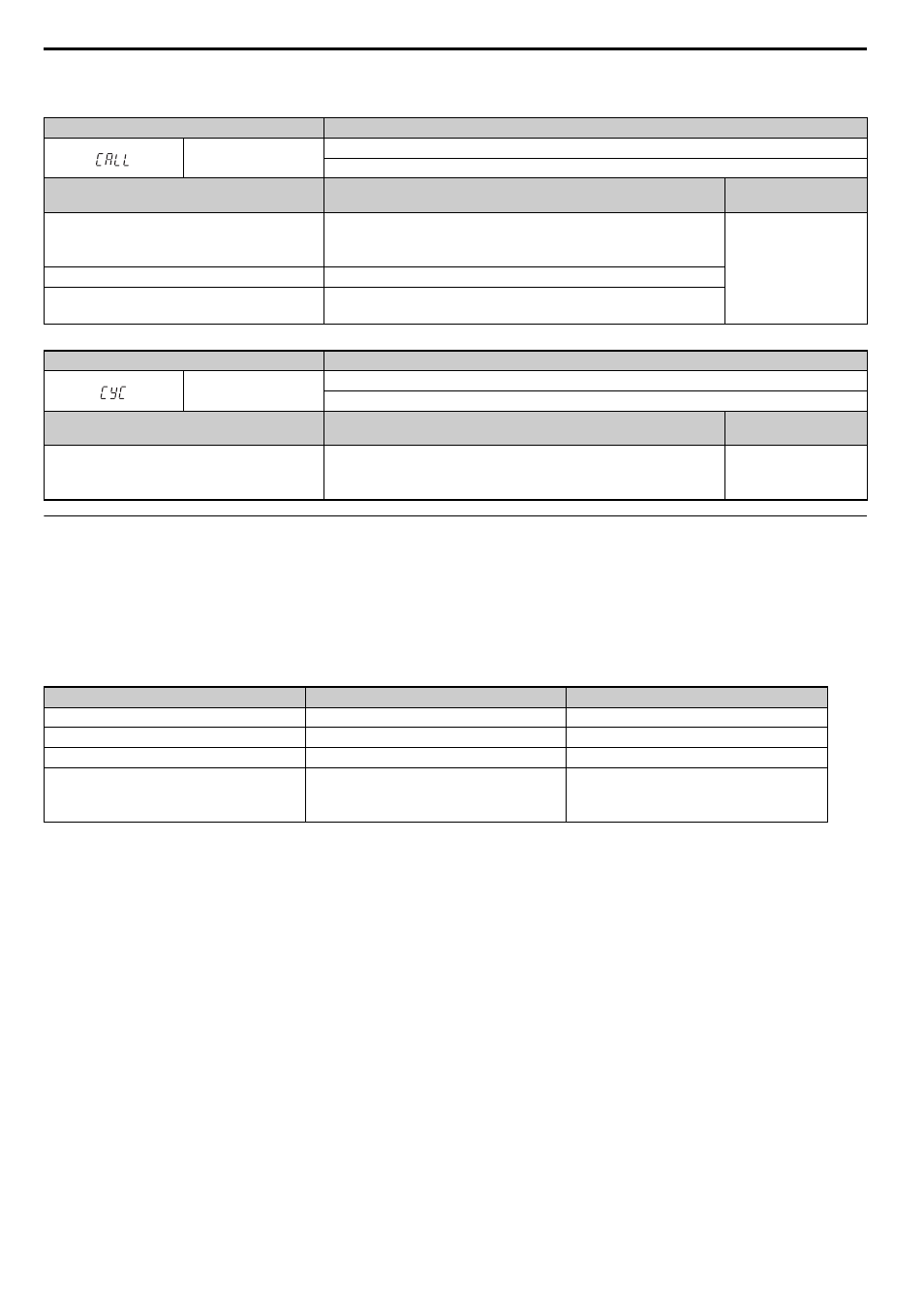
LED Operator Display
Minor Fault Name
CALL
Serial communication transmission error
Communication is not established.
Cause
Possible Solution
Minor Fault
(H2- = 10)
Communication wiring is faulty, there is a short
circuit, or improper connection.
Check for wiring errors:
• Correct the wiring
• Remove ground shorts and reconnect loose wires
YES
Programming error on the master side.
Check communications at start-up and correct programming errors.
Communication circuitry is damaged.
• Perform a self-diagnostics check
• Replace the drive if the fault continues to occur
LED Operator Display
Minor Fault Name
CYC
Transmission Cycle Setting Error
Transmission cycle from the master controller (PLC) was out of range.
Cause
Possible Solution
Minor Fault
(H2- = 10)
Transmission cycle of the option set in the
master controller (PLC) was out of range.
Set the transmission cycle of the master controller in the range of 250
μs, 500 μs, 750 μs, and 1 to 32 ms (0.5 ms increment). Make sure to
set the communication cycle to 32 ms or less.
YES
Option Card
<1> If two PG option cards are connected, use both CN5-B and CN5-C. If only one PG option card is connected to the drive, use the CN5-C
connector.
<2> These option cards are not available for the application with Motor 2 Selection.
<3> These option cards are not available with models CIMR-A4A0930 and 4A1200.
<4> When AI-A3 and DI-A3 are to be used as monitors, the card can be connected to any of CN5-A, CN5-B or CN5-C. The input status of
AI-A3 can then be viewed using U1-21, U1-22, and U1-23, and the input status of DI-A3 can then be viewed using U1-17.
Connector
Number of Cards Possible
PG-B3, PG-X3
CN5-C
2
PG-RT3
, PG-F3
CN5-C
1
DO-A3, AO-A3
CN5-A, B, C
1
SI-C3, SI-N3, SI-P3, SI-S3, SI-T3, SI-ET3,
AI-A3, DI-A3, SI-ES3, SI-B3, SI-M3,
SI-W3, SI-EM3, SI-EN3, SI-EP3
CN5-A
1