A1000 – Yaskawa SI-ET3 User Manual
Page 14
5 Installation Procedure
14
YASKAWA ELECTRIC SIEP C730600 62B 1000-Series Option SI-ET3 Technical Manual
5.
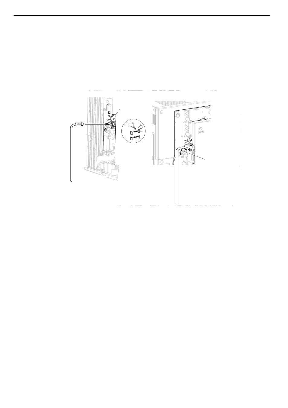
Route the option wiring.
Depending on the drive model, some drives may require routing the wiring through the side of the front cover to
the outside to provide adequate space for the wiring. Refer to the Peripheral Devices & Options section of the
drive Quick Start Guide or instruction manual for more information on wire routing of specific models.
Route the wiring through the side of the front cover to the outside. In these cases, using diagonal cutting pliers,
cut out the perforated openings on the left side of the drive front cover as shown in
-A. Sharp edges
along the cut out should be smoothed down with a file or sand paper to prevent any damage to the wires.
Route the wiring inside the enclosure as shown in
-B for drives that do not require routing through the
front cover.
Note: Separate communication cables from main circuit wiring and other electrical lines.
Figure 7
Figure 7 Wire Routing Examples
6.
Connect the MECHATROLINK-III communication cable to option communication connector CN1 or CN2. Refer
to
Communication Cable Wiring on page 15
for details.
Install MECHATROLINK-III communications cables apart from main-circuit wiring and other electrical and power
lines. Ensure the cable end is firmly connected (see
).
Note: Maximum transmission distance is 100 m (3937.0 in.). Minimum wiring distance between stations is 0.2 m (7.9 in.).
A – Route wires through the openings
provided on the left side of the
front cover.
<1> The drive will not meet NEMA Type 1 requirements if wiring is exposed outside the enclosure.
B – Use the open space provided
inside the drive to route option
wiring.
B
A
A1000