For det, A1000, 5 installation procedure – Yaskawa SI-ET3 User Manual
Page 15: Connection diagram
5 Installation Procedure
YASKAWA ELECTRIC SIEP C730600 62B 1000-Series Option SI-ET3 Technical Manual
15
Connection Diagram
Figure 8 Option Connection Diagram
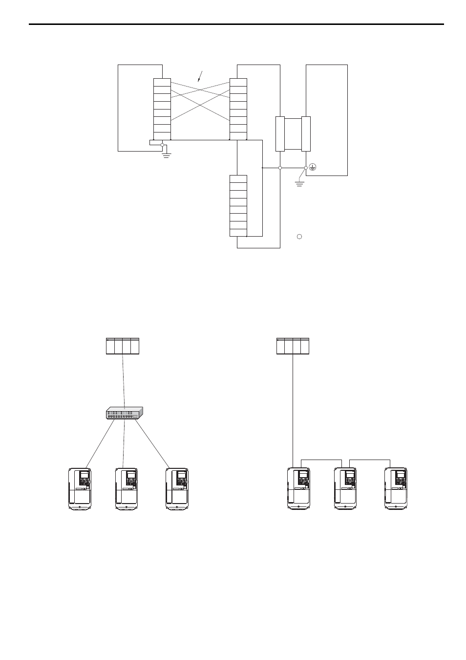
Communication Cable Wiring
The dual communication cable ports on the option board act as a switch to allow for flexibility in cabling topology.
For example, a traditional star network topology may be employed by using a single port on the option board.
Alternatively, a daisychained approach may be employed by using both communication cable ports. This second
approach reduces the requirements of MECHATROLINK-III hub module ports.
Figure 8
Figure 9 Topology Options
<1> Use connector CN1 or CN2 to connect with the MECHATROLINK-III master. Refer to
A1000
TXD_P
TXD_N
RXD_P
NC
NC
RXD_N
NC
NC
TXD_P
TXD_N
RXD_P
NC
NC
RXD_N
NC
NC
MECHATROLINK-III
Master
SI-ET3
CN2
<1>
TXD_P
TXD_N
RXD_P
NC
NC
RXD_N
NC
NC
CN1
<1>
FE
Drive
control circuit terminal
MECHATROLINK-III
Communication Cable
PLC
MECHATROLINK-III
Hub Module
A1000
A1000
A1000
A1000
A1000
A1000
PLC
A1000