4 option components, Si-et3 option, Connector – Yaskawa SI-ET3 User Manual
Page 8: 4option components, A1000
8
YASKAWA ELECTRIC SIEP C730600 62B 1000-Series Option SI-ET3 Technical Manual
4 Option Components
4
Option Components
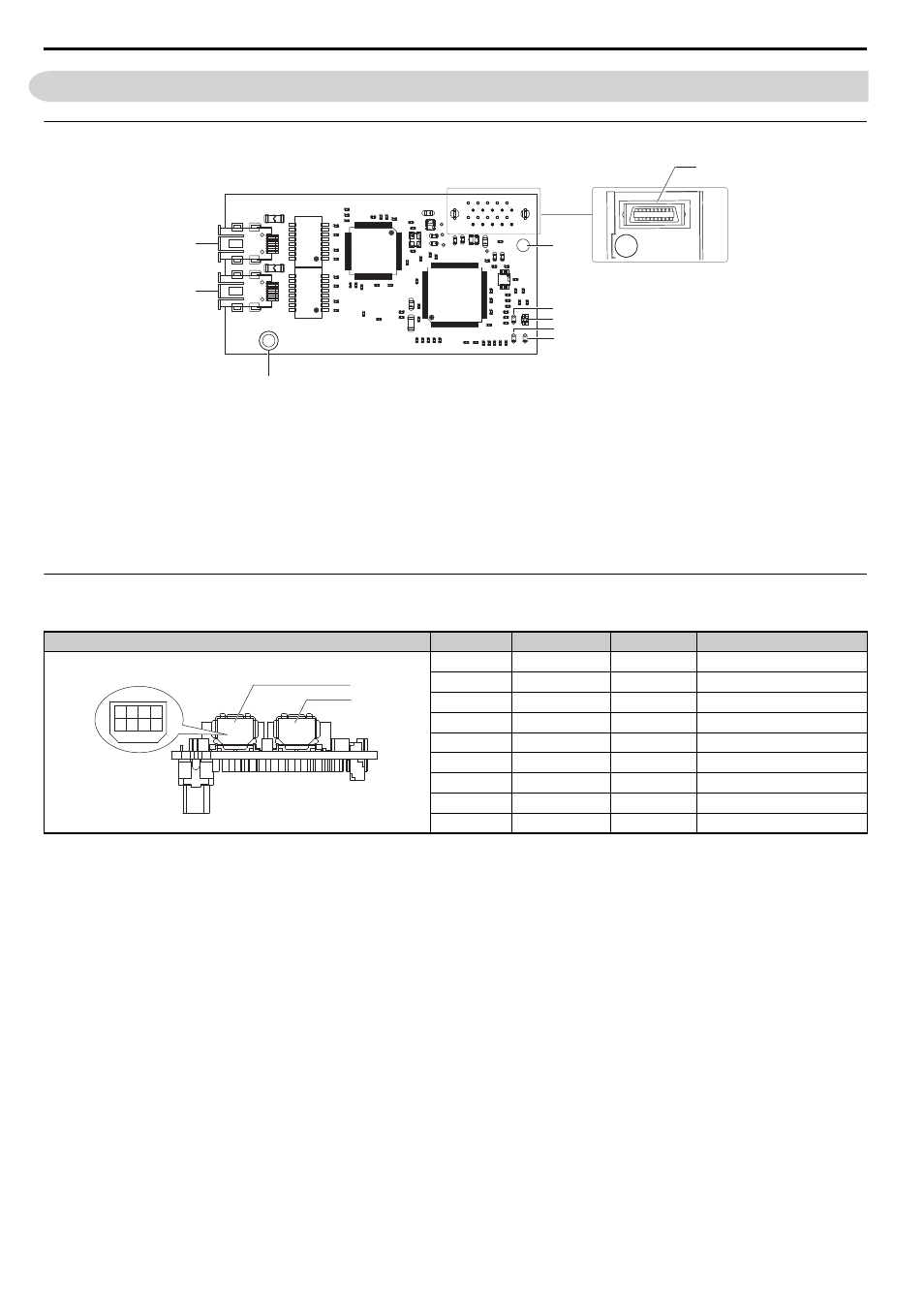
SI-ET3 Option
Figure 1
Figure 1 SI-EN3 Option Components
Connector
Table 3 Communication Connector
A – Connector (CN5)
<1>
Refer to Option LED Display on page 9
for details on the LEDs
<2> The ground wire provided in the option shipping package must be connected during installation
F – LED (LK1)
B – Installation hole
G – Ground terminal and installation hole
C – LED (CON)
H – Communication connector CN1
D – LED (R/E)
I – Communication connector CN2
E – LED (LK2)
MECHATROLINK-III Connector
Pin No.
Signal Name
I/O
Function
1
TXD_P
I/O
Send data (+): OUT
2
TXD_N
I/O
Send data (-): OUT
3
RXD_P
I/O
Receive data (-): IN
4
(NC)
–
–
5
(NC)
–
–
6
RXD_N
I/O
Receive data (-): IN
7
(NC)
–
–
8
(NC)
–
–
Shell
SLD
–
Shield
A1000
E
F
G
H
I
D
C
B
Underside
A
A1000
2 4 6 8
1 3 5 7
CN2
CN1