A1000, 5 installation procedure – Yaskawa SI-ET3 User Manual
Page 13
5 Installation Procedure
YASKAWA ELECTRIC SIEP C730600 62B 1000-Series Option SI-ET3 Technical Manual
13
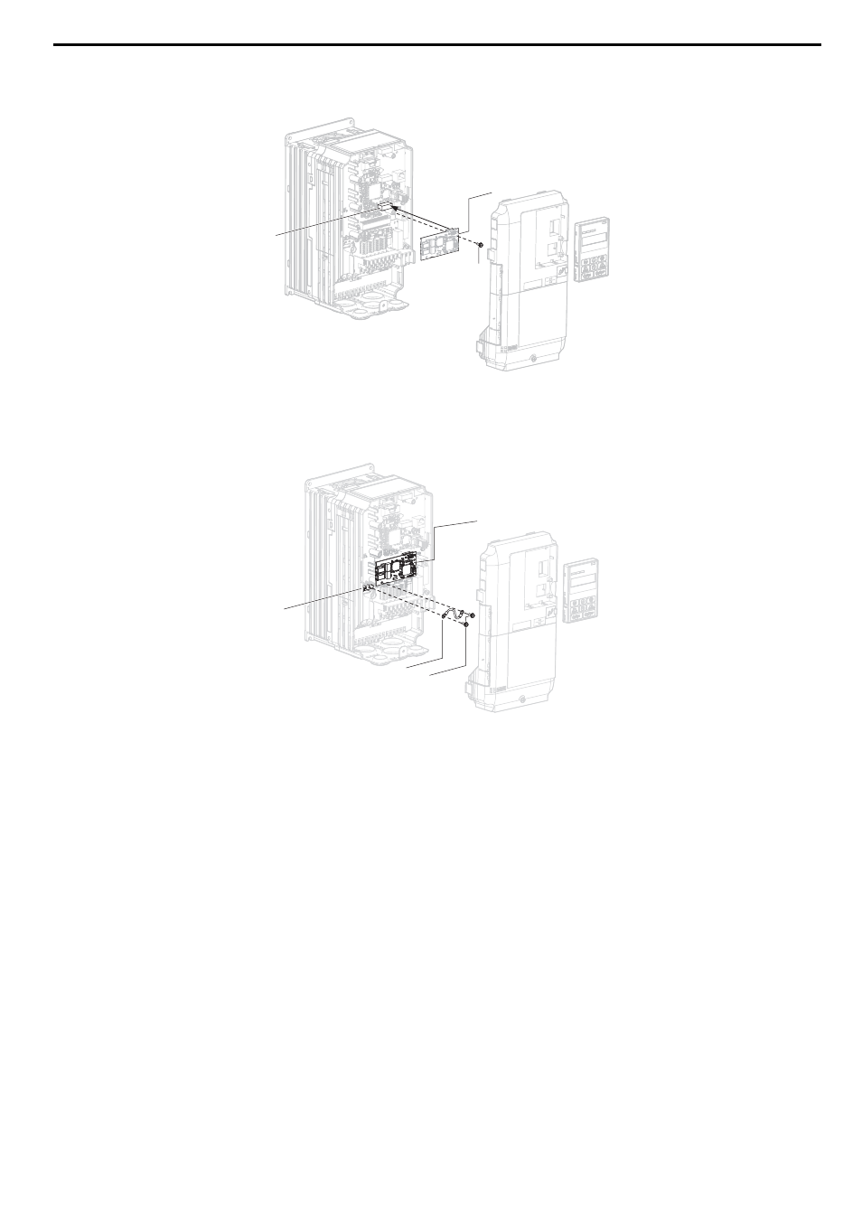
3.
Insert the option (B) into the CN5-A connector (M) located on the drive and fasten it using one of the included
screws (H).
Figure 5
Figure 5 Insert the Option
4.
Connect the ground wire (I) to the ground terminal (L) using one of the remaining provided screws (H). Connect
the other end of the ground wire (I) to the remaining ground terminal and installation hole on the option (B) using
the last remaining provided screw (H) and tighten both screws to 0.5 to 0.6 Nxm (4.4 to 5.3 in lbs).
Figure 6
Figure 6 Connect the Ground Wire
Note: There are two screw holes on the drive for use as ground terminals (L). When connecting three options, two ground wires will
need to share the same drive ground terminal.
NS
MS
M
H
B
A1000
NS
MS
H
I
L
B
A1000