Figure 5: wiring example of els with alignment, G7 drive with els, Pg -w2 opt ion card – Yaskawa G7 Drive User Manual
Page 25
Date: 03/31/09, Rev: 09-03
Page 25 of 30
TM.G7SW.064
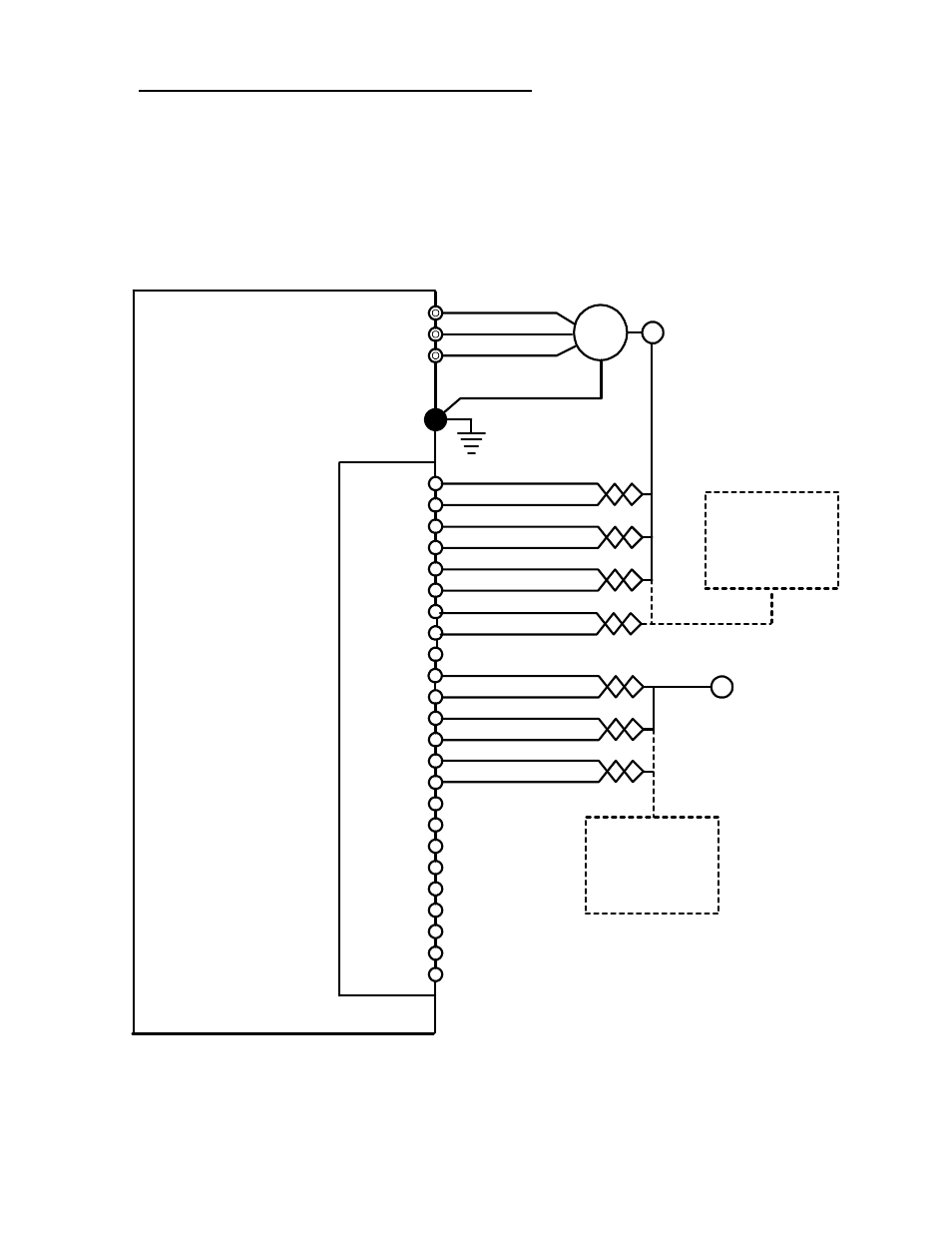
5.4 Wiring Electronic Lineshaft and the Alignment Inputs
The two alignment inputs can each come from either the marker pulse from an encoder or from an external
sensor. The alignment inputs need to be wired to the marker (Z) pulse inputs of the dual input encoder card
(ex. PG-W2). Marker pulse input channels require a line driver type circuit. Wire the master alignment input
into terminals 14 and 15 of the PG-W2. Wire the follower alignment input into terminals 7 and 8 of the PG-
W2. For other dual input encoder cards, consult their installation guide for exact terminals. Figure 5 below
details the wiring of the PG-W2 option card.
IM
12VDC Supply
Common
A+
A-
B+
B-
1
2
3
4
5
6
7
8
9
GND
P
G
-W2 Opt
ion
Card
T1
T2
T3
Motor
11
12
13
14
15
16
A+
A-
B+
B-
10
17
18
19
20
21
22
23
24
Z-
Z+
Follower
Encoder
Master
Encoder
Note: An external power supply may be
required to power the master encoder.
The PG-W2 has a 200mA power supply.
Check the rated current of both encoders.
External
Master
Alignment
Sensor
G7 Drive
with ELS
Z-
Z+
External
Follower
Alignment
Sensor
Figure 5: Wiring Example of ELS with Alignment