Yaskawa G7 Drive User Manual
Page 5
Date: 03/31/09, Rev: 09-03
Page 5 of 30
TM.G7SW.064
2.0 Changes from Standard Product
a. The Motor 2 Selection (H1-0X = 16) multi-function digital input function is deleted (only Motor 1 can be
used).
b. The kWh monitors (U1-29 and U1-30) are deleted.
c. Parameter E2-04 (Motor Poles) is available in all control modes (Advanced access level only for V/f and
Open Loop Vector).
d. The “User” access level and all of the associated “A2” parameters are deleted.
e. The follower drive uses acceleration and deceleration times of zero during standard Electronic Line Shaft
(P1-01 = 4, 5) and the Alignment function.
3.0 Limitations
a. For ELS modes (P1-01 = 4, 5), Flux Vector control mode must be used (A1-02 = 3).
b. For ELS modes (P1-01 = 4, 5), the gear ratio must be exactly expressed, including remainder, to prevent
phase drift (error). See section 5.0.
c. The Alignment function is available in Flux Vector control mode only (A1-02 = 3) and when P1-01 = 4 or 5
(ELS modes).
d. The Alignment function is only available in the forward direction.
e. The Alignment function is disabled when the motor speed is less than the DC Injection
Frequency (B2-01).
f. The alignment pulse from the master and the alignment pulse from the slave must be at a 1:1 ratio (the
software requires one follower alignment pulse for every one master alignment pulse).
g. The master alignment pulse must occur exactly once per master encoder revolution.
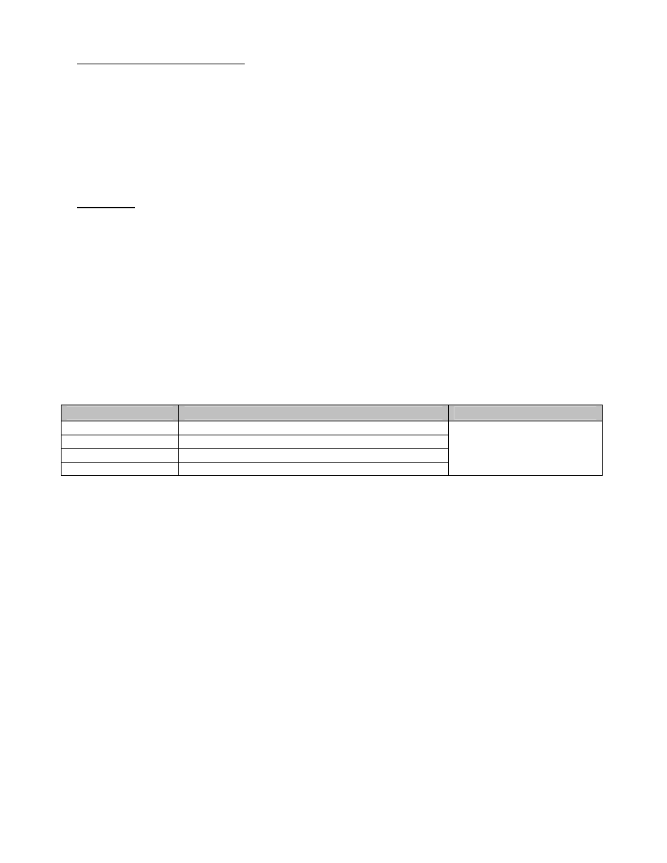
h. The proper encoder (PG) option card must be used based on the control mode and follower mode
selection. The table below shows the supported option cards for each configuration.
Encoder (PG) Option Card Selection
Control Mode
P1-01 = 1, 2, 3 (Speed Follower)
P1-01 = 4, 5 (ELS)
V/f
PG-B2, PG-T2, PG-X2, PG-W2, PG-Y2, PG-Z2
V/f w/ PG
PG-W2, PG-Y2, PG-Z2
Open Loop Vector
PG-B2, PG-T2, PG-X2, PG-W2, PG-Y2, PG-Z2
Flux Vector
PG-W2, PG-Y2, PG-Z2
PG-W2, PG-Y2, PG-Z2
Note: If the PG-W2 option is used, jumper HDR1 must be set to the “top” position
(using the 2 pins closest to the 4CN connector).