Figure 8: composite gear ratio diagram – Yaskawa G7 Drive User Manual
Page 28
Advertising
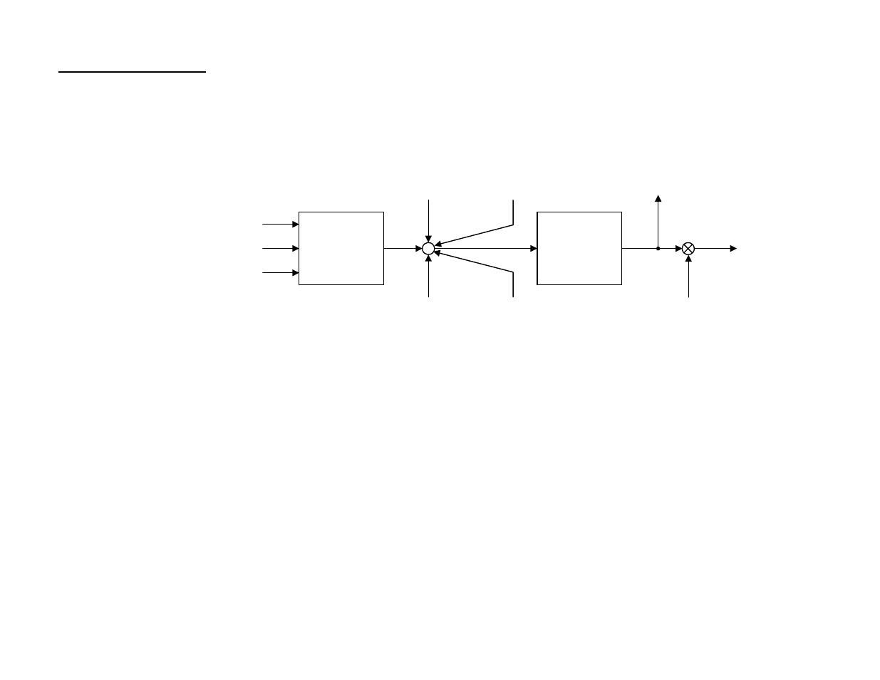
6.0 Block Diagrams (continued)
MOP
Adjustment
MOP Increase (H1-XX = 84)
MOP Decrease (H1-XX = 85)
MOP Reset (H1-XX = 86)
Digital Ratio
Adjustment
(P2-01)
Analog Ratio
Adjustment
H3-05/09 = 20
Network Communication
Ratio Adjustment
(Modbus Register 61CH)
100%
+
+
+
+
+
Gear Ratio
Adjustment
(U1-92)
Gear Ratio
Adjustment
Ramp Time
(P2-03)
Follower
Reference After
Gear Ratio
(U1-91)
Follower
Reference After
Gear Ratio
Adjustment
(U1-93)
Figure 8: Composite Gear Ratio Diagram
Date: 03/31/09, Rev: 09-03
Page 28 of 30
TM.G7SW.064
Advertising
This manual is related to the following products: