G7 w/ els – Yaskawa G7 Drive User Manual
Page 3
Date: 03/31/09, Rev: 09-03
Page 3 of 30
TM.G7SW.064
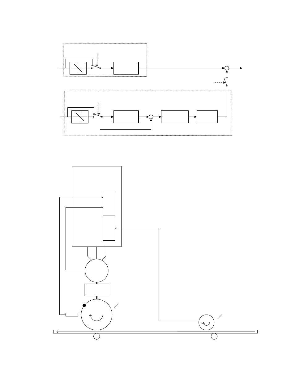
Figure 1: Simplified Block Diagram of the Electronic Lineshaft Function
Figure 2: Typical Connection Diagram of the Alignment Function
Gear
Calculation
Gear
Calculation
Master Encoder
Speed
Master Encoder
Pulse Count
Follower Encoder
Pulse Count
+
-
+
+
PI
Controller
Frequency
Reference
ELS Mode Enabled OR
ELS – Sign Mode
Enabled
Position Error
Accumulator
Speed Calculation
Position Regulator
ELS – Sign Mode Enabled
AND Reverse Run Command
ELS – Sign Mode Enabled
AND Reverse Run Command
G7 w/ ELS
PG-W2
Ch 1
Gear Box
Motor
A, B
Follower
Encoder
Feedback
Z
Alignment
Input
A, B, Z
Ch 2
Proximity
Sensor for
Follower
Master
Encoder
Feedback
ith Marker
Pulse for
Master
Follower
Machine
w
Alignment
Section
Master
Machine
Input
Section