3 encoder signal output – Yaskawa LEGEND Digital Torque Amplifier User Manual
Page 55
4.3 Encoder Signal Output
44
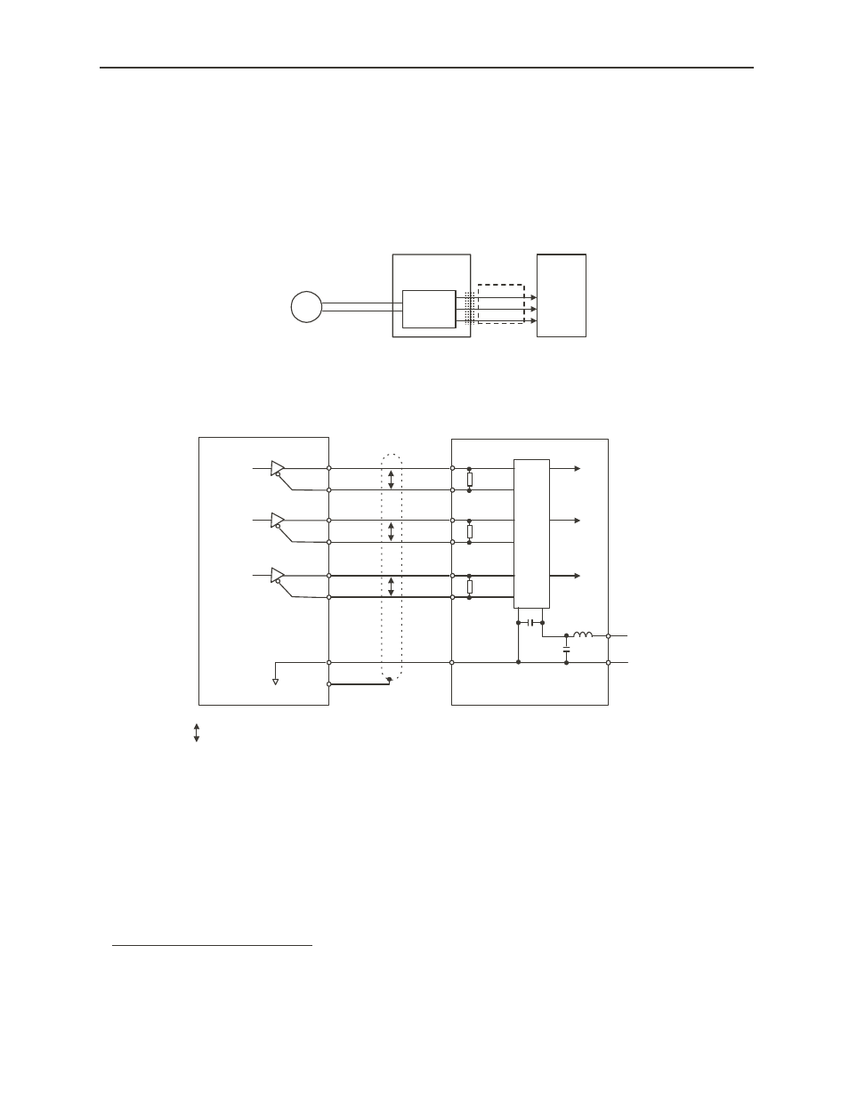
4.3 Encoder Signal Output
The output signal following division within the digital torque amplifier of the encoder output
1
can be output to an external device.
The output circuit is a line driver output. Connect in consideration of the following
circuit.
1. After Division: This means the output converted to the set pulse ratio based on the pulse data from the
encoder mounted on the motor. The unit here is “No. of Pulses/Rotation”.
PG
Digital Torque
Amplifier
CN2
CN1
Encoder
Upper-Level
Device
A-Phase
B-Phase
C-Phase
Serial Data
Division
Circuit
Digital Torque
Amplifier
Line Receiver
Upper-Level Device
A-Phase
PAO
*PAO
R
‚o
2
CN1-20
A-Phase
3
1
CN1-21
B-Phase
PBO
*PBO
R
‚o
6
CN1-22
B-Phase
5
7
CN1-23
C-Phase
PCO
*PCO
R
‚o
10
CN1-24
C-Phase
11
9
CN1-25
Choke
Coil
8
‚b
OV
16
+5
V
+
-
Smoothing
Capacitor
0V
+5
V
CN1-1
Connector Shell
OV
Shield Wire
‚o: Shows a twisted pair wire.
Applied Line Receiver: TI SN75175 or MC3486-
equivalent
R (Termination Resistance): 220~470Ħ
‚b (Decoupling Capacitor) : 0.1ƒÊF