Main circuit wiring, Main circuit terminal functions – Yaskawa AC Drive-L1000E Safety Precautions User Manual
Page 16
5 Electrical Installation
16
YASKAWA TOEP YAIL1E 02A YASKAWA AC Drive - L1000E Safety Precautions
Main Circuit Wiring
WARNING! Do not connect the AC power line to the output motor terminals of the drive. Failure to comply could result in death or
serious injury by fire as a result of drive damage from line voltage application to output terminals. Do not connect AC line power to
output terminals U, V, and W. Make sure that the power supply lines are connected to main circuit input terminals R/L1, S/L2, T/L3 (or
R/L1 and S/L2 for single-phase power).
NOTICE: Equipment Hazard. Separate motor and/or braking circuit wiring (terminals, U/T1, V/T2, W/T3, +3, +2, +1,(-), B1, B2, from all
other wiring. Place motor wiring within its own conduit or cable tray with appropriate divider, and use shielded motor cable where
appropriate. Improper wiring practices could result in malfunction of drive due to electrical interference.
NOTICE: Route motor leads U/T1, V/T2, and W/T3 separate from all other leads to reduce possible interference related issues. Failure
to comply may result in abnormal operation of drive and nearby equipment.
NOTICE: Equipment Hazard. Separate motor and/or braking circuit wiring (terminals, U/T1, V/T2, W/T3, +3, +2, +1,(-), B1, B2, from all
other wiring. Place motor wiring within its own conduit or cable tray with appropriate divider, and use shielded motor cable where
appropriate. Improper wiring practices could result in malfunction of drive due to electrical interference.
NOTICE: Do not use the negative DC bus terminal “–” as a ground terminal. This terminal is at high DC voltage potential. Improper
wiring connections could damage the drive.
NOTICE: Do not solder the ends of wire connections to the drive. Soldered wiring connections can loosen over time. Improper wiring
practices could result in drive malfunction due to loose terminal connections.
NOTICE: Do not switch the drive input to start or stop the motor. Frequently switching the drive on and off shortens the life of the DC
bus charge circuit and the DC bus capacitors, and can cause premature drive failures. For the full performance life, refrain from
switching the drive on and off more than once every 30 minutes.
NOTICE: When connecting the motor to the drive output terminals U/T1, V/T2, and W/T3, the phase order for the drive and motor
should match. Failure to comply with proper wiring practices may cause the motor to run in reverse if the phase order is backward.
NOTICE: Do not connect phase-advancing capacitors or LC/RC noise filters to the output circuits. Failure to comply could result in
damage to the drive, phase-advancing capacitors, LC/RC noise filters or ground fault circuit interrupters.
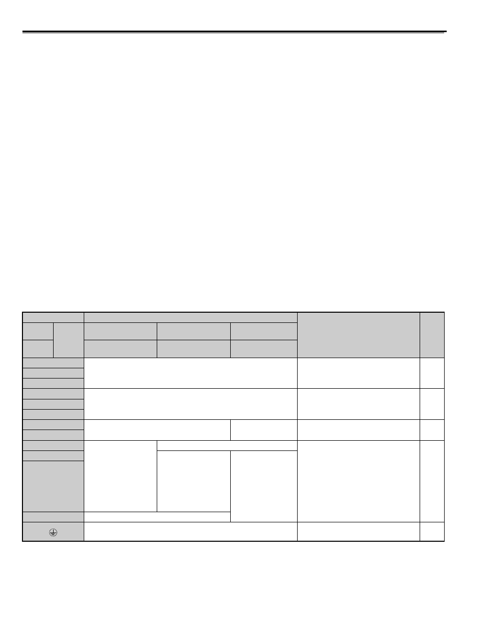
Main Circuit Terminal Functions
Table 4 Main Circuit Terminal Functions
Note: Use terminal B1 and - when installing the braking unit (CDBR type) to the drives with built-in braking transistor (2A0018 to
2A0144, 4A0009 to 4A0075).
Terminal
Type
Function
Page
200 V
Class
Drive
Model
2A0018 to 2A0094
2A0106, 2A0144
2A0181 to 2A0432
400 V
Class
4A0009 to 4A0049
4A0056, 4A0075
4A0094 to 4A0260
R/L1
Main circuit power supply input
Connects line power to the drive
S/L2
T/L3
U/T1
Drive output
Connects to the motor
V/T2
W/T3
B1
Braking resistor
Not available
Available for connecting a braking
resistor or a braking resistor unit option
–
B2
+2
• DC link choke
connection (+1, +2)
(remove the shorting
bar between +1 and
+2)
• DC power supply
input
(+1, –)
not available
For connection
• of the drive to a DC power supply
(terminals +1 and – are not UL
approved)
• of dynamic braking options
–
+1
• DC power supply
input
(+1, –)
• DC power supply
input (+1, –)
• Braking unit
connection (+3, –)
–
+3
not available
For 200 V class: 100
Ω or less
For 400 V class: 10
Ω or less
Grounding terminal