7 start up, Start up, 7start up – Yaskawa AC Drive-L1000E Safety Precautions User Manual
Page 35
7 Start Up
YASKAWA TOEP YAIL1E 02A YASKAWA AC Drive - L1000E Safety Precautions
35
7
Start Up
L1000E parameter configuration is not possible with the supplied JVOP-184. This Start-up procedure may not be
required if your L1000E is part of a pre-configured OEM supplied system.
An optional (Digital Operator JVOP-180) is required to perform the following Start-up procedure or additional L1000E
configuration. Contact your OEM or local Yaskawa representative if the JVOP-180 Digital Operator is required for your
application. Refer to the L1000E Quick Start Guide or Technical Manual for complete L1000E technical information.
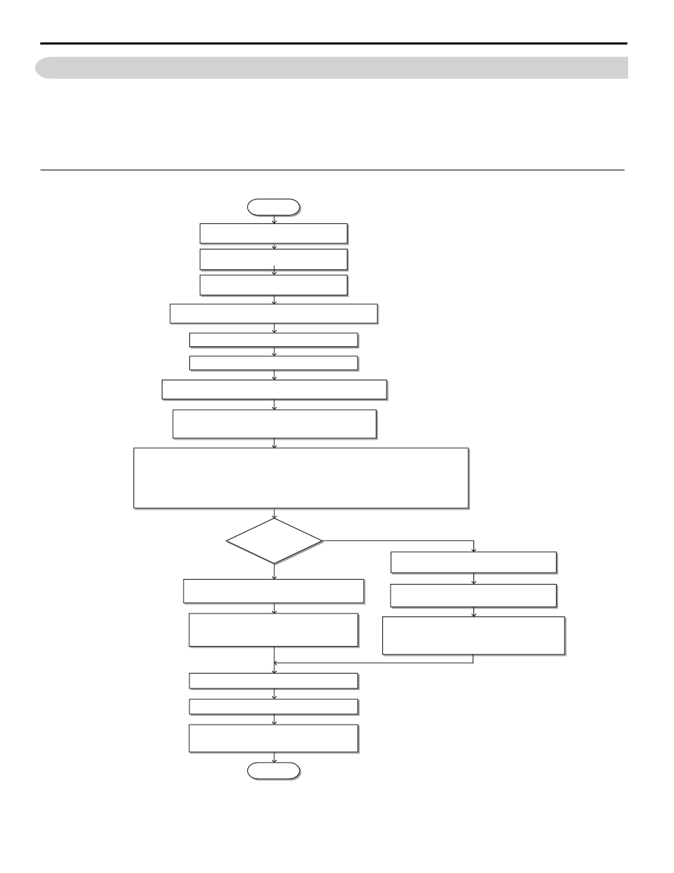
Flowchart A: Installation, Wiring, Basic Setup for Motor and Elevator
Figure 19
Figure 19 Installation, Wiring, Basic Setup for Motor and Elevator
Note: Set parameter H5-11 to 1 when setting parameters using MEMOBUS/Modbus communications.
For control modes below, refer to the Quick Start Guide or Technical Manual
• V/f Control
• Open Loop Vector Control
• Closed Loop Vector Control
• Closed Loop Vector for PM Control
START
Install the drive as explained in this document
or the Quick Start Guide/Technical Manual
Wire the drive as explained in in this document
or the Quick Start Guide/Technical Manual
Check the PG encoder power supply selection.
(Closed Loop Vector Control only -CLV)
Apply main power to the drive.
Adhere to safety messages concerning application of power.
Perform Auto-Tuning for motor parameters and the PG encoder offset.
Determine the
source of the speed
reference.
Analog Input
Digital operator (b1-01 = 0)
(Speed selection by digital inputs)
Assign functions to the analog/digital I/O terminals using
parameters H1-
, H2-
, H3-
, and H4-
.
Set up:
• Acceleration/deceleration ramp (C1-
)
• Jerk settings (C2-
)
Perform a test run.
Fine-tuning
• Adjust settings for the brake sequence (S1-
) .
• Adjust speed control loop (C5-
) etc.
FINISH
Set up:
• Preset speed references (d1-
)
• Acceleration/deceleration ramp (C1-
)
• Jerk settings (C2-
)
Assign functions to the digital I/O terminals using
parameters H1-
and H2-
.
Set the Speed Reference Selection mode
parameter d1-18.
Set the Unit Length in parameter o1-12.
Set up o1-20 to o1-22 and then select the display units for speed,
acceleration and deceleration ramp and jerk settings in o1-03.
Set up the Inspection Operation sequence.
Set up the PG encoder feedback in F1-
parameters when using a
Closed Loop Vector Control and check the PG encoder rotation direction.
Select the control mode in parameter A1-02.
Check the motor rotation direction.