Wiring the control circuit terminal – Yaskawa AC Drive-L1000E Safety Precautions User Manual
Page 31
5 Electrical Installation
YASKAWA TOEP YAIL1E 02A YASKAWA AC Drive - L1000E Safety Precautions
31
Wiring the Control Circuit Terminal
This section describes the proper procedures and preparations for wiring the control terminals.
DANGER! Do not change wiring, remove covers, connectors or options cards, or attempt to service the drive with power applied to the
drive. Disconnect all power to the drive, and lock out the power source. After shutting off the power wait for at least the amount of time
specified on the drive front cover safety label. Measure the DC bus voltage for unsafe voltages to confirm safe level before servicing to
prevent electric shock. The internal capacitor remains charged even after the power supply is turned off. Failure to comply will result in
serious injury or death from electric shock.
WARNING! Electrical Shock Hazard. Do not remove covers or touch the circuit boards while the power is on. Failure to comply could
result in death or serious injury.
WARNING! Electrical Shock Hazard. Before servicing, disconnect all power to the equipment and lock out the power source. Failure to
comply may result in injury from electrical shock. Wait at least five minutes after all indicators are OFF and measure the DC bus voltage
level and main circuit terminals to confirm the circuit is safe before wiring.
WARNING! Sudden Movement and Hazard. Install additional emergency circuits separately from the drive fast stop circuits. Failure to
comply may result in personal injury.
WARNING! Do not tighten screws beyond the specified tightening torque. Failure to comply may result in erroneous operation, damage
the terminal block, or cause injury due to fire from overheating of loose electrical connections.
NOTICE: Separate control circuit wiring from main circuit wiring (terminals R/L1, S/L2, T/L3, B1, B2, U/T1, V/T2, W/T3, -, +1, +2) and
other high-power lines. Improper wiring practices could result in drive malfunction due to electrical interference.
NOTICE: Separate wiring for output terminals MA, MB, MC, M1 and M2 from wiring to other control circuit lines. Improper wiring
practices could result in drive or equipment malfunction or nuisance trips.
NOTICE: Use a class 2 power supply (UL standard) when connecting to the control terminals. Improper application of peripheral
devices could result in drive performance degradation due to improper power supply.
NOTICE: Equipment Hazard. Insulate shields with heat shrink tubing or tape to prevent contact with other signal lines and equipment.
Improper wiring practices could result in drive or equipment malfunction due to short circuit.
NOTICE: Connect the shield of shielded cable to the appropriate ground terminal. Improper equipment grounding could result in drive
or equipment malfunction or nuisance trips.
NOTICE: Equipment Hazard. Use twisted-pair or shielded twisted-pair cables for control circuits. Improper wiring practices could result
in drive or equipment malfunction or nuisance trips.
Wire the control circuit only after terminals have been properly grounded and main circuit wiring is complete. Refer to
for details. Prepare the ends of the control circuit wiring as shown in
. Refer to
Size and Torque Specifications on page 30
Connect control wires as shown in
.
Figure 12
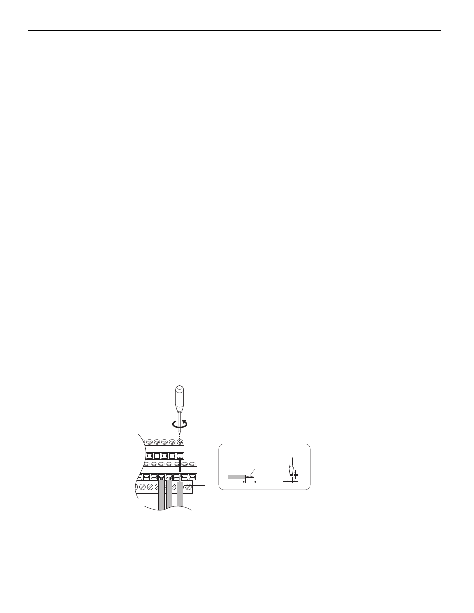
Figure 12 Terminal Board Wiring Guide
A – Loosen screw to insert wire
C – Avoid fraying wire strands when stripping
insulation from wire. Strip length 5.5 mm (0.22 in.)
B – Single wire or stranded wire
D – Blade depth of 0.4 mm (0.02 in.) or less
Blade width of 2.5 mm (0.10 in.) or less
A
B
C
D
Preparing wire
terminal ends