En81-1 compliant circuit with one motor contactor – Yaskawa AC Drive-L1000E Safety Precautions User Manual
Page 48
9 Standards Compliance
48
YASKAWA TOEP YAIL1E 02A YASKAWA AC Drive - L1000E Safety Precautions
Digital Operator Display
In contrast to terminals DM+/DM-, the safe disable monitor function that can be programmed for a digital output (H2-
= 58) is a software function and can be used for EN81-1 conform one contactor solutions but not as an EDM signal
according to EN61800-5-1.
When both Safe Disable inputs are open, "Hbb" will flash in the digital operator display.
Should only one of the Safe Disable channels be on while the other is off, "HbbF" will flash in the display to indicate that
there is a problem in the safety circuit or in the drive. This display should not appear under normal conditions if the Safe
Disable circuit is utilized properly.
Refer to Alarm Codes, Causes, and Possible Solutions on page 132
to resolve
possible errors.
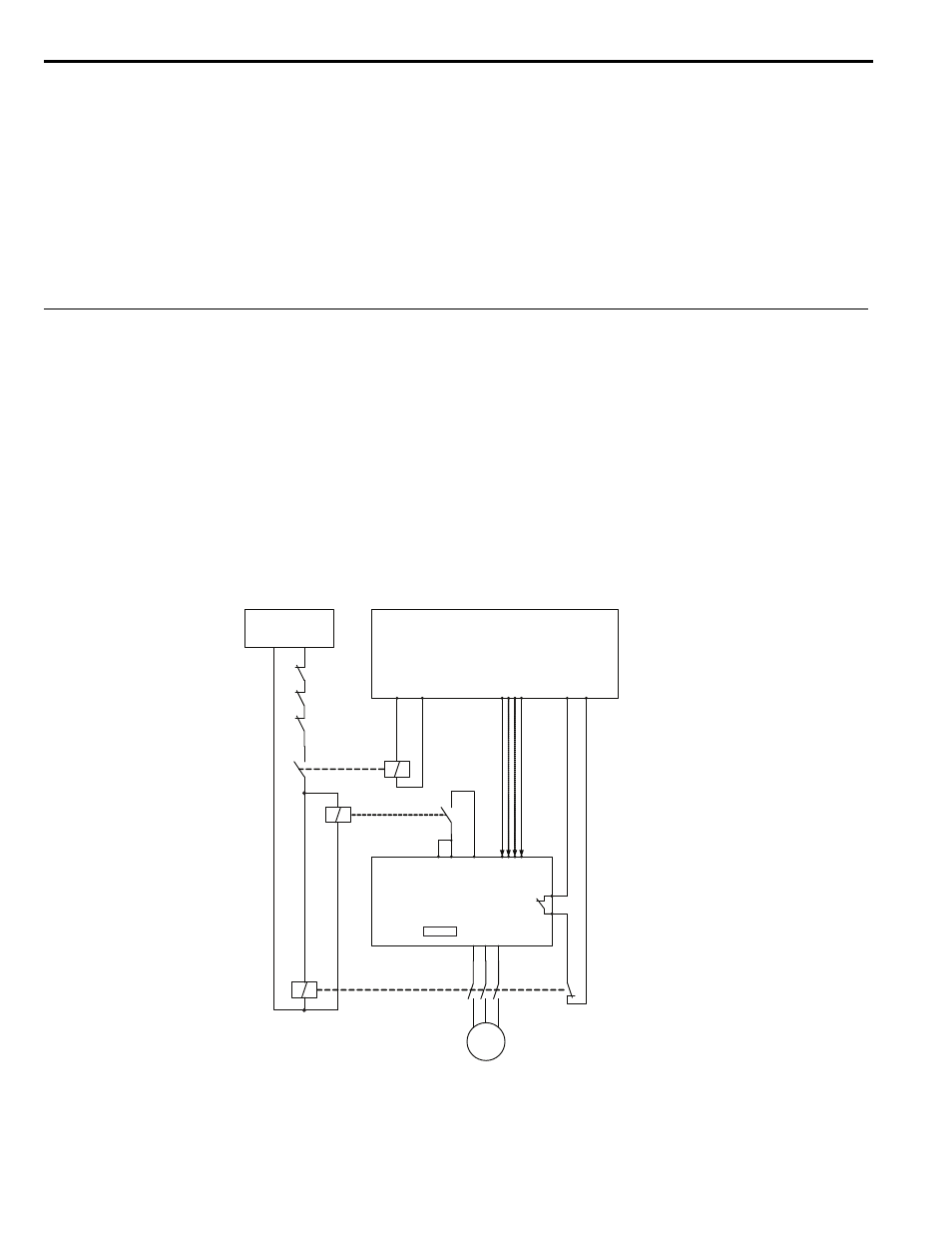
EN81-1 Compliant Circuit with one Motor Contactor
The safe disable circuit can be utilized to install the drive in an elevator system using only one motor contactor instead of
two. In such a system the following guidelines have to be followed for compliance to EN81-1:1998:
• The circuit must be designed so that the inputs H1 and H2 are opened and the drive output shuts off when the safety
chain is interrupted.
• A drive digital output must be programmed as Safe Disable feedback (H2- = 58). This feedback signal must be
implemented in the contactor supervision circuit of the controller that prevents a restart in case of a fault in the Safe
Disable circuit or the motor contactor.
• All contactors and wiring must be selected and installed in compliance with the EN81-1:1998.
• The safe disable inputs H1 and H2 must be used to enable/disable the drive. The input logic must be set to Source
Mode.
Refer to Sinking/Sourcing Mode Selection for Safe Disable Inputs on page 48
for details on setting jumper S3.
The figure below shows a wiring example.
Note: 1. The drive output will immediately shut off when either of the inputs H1 or H2 is opened. In this case the brake should apply
immediately in order to prevent uncontrolled movement of the elevator.
2. The drive output can only be activated when neither an Up nor a Down command is active, i.e., terminals H1 and H2 must be closed
prior to setting the Up/Down command.
Safety Chain
Circuit
Elevator Controller
Contactor Close
Command
Contactor Check
(Restart Permission)
K01
24 Vdc
K1
H1 H2
Up/Down;
Speed selection; ...
Safe Disable Monitor
(H2-
= 58)
Yaskawa
CIMR-L
K2
M
HC
Drive