N in, Figure 13, Switches and jumpers on the terminal board – Yaskawa AC Drive-L1000E Safety Precautions User Manual
Page 32
5 Electrical Installation
32
YASKAWA TOEP YAIL1E 02A YASKAWA AC Drive - L1000E Safety Precautions
When connecting control wires to the terminals, use shielded twisted-pair wires (treating wire ends as shown in
and connect the shield to the ground terminal (E [G]) of the drive.
NOTICE: Equipment Hazard. Insulate shields with heat shrink tubing or tape to prevent contact with other signal lines and equipment.
Improper wiring practices could result in drive or equipment damage due to short circuit
Figure 13
Figure 13 Preparing the Ends of Shielded Cables
NOTICE: Do not exceed 50 meters (164 ft.) for the control line between the drive and the operator when using an analog signal from a
remote source to supply the frequency reference. Failure to comply could result in poor system performance.
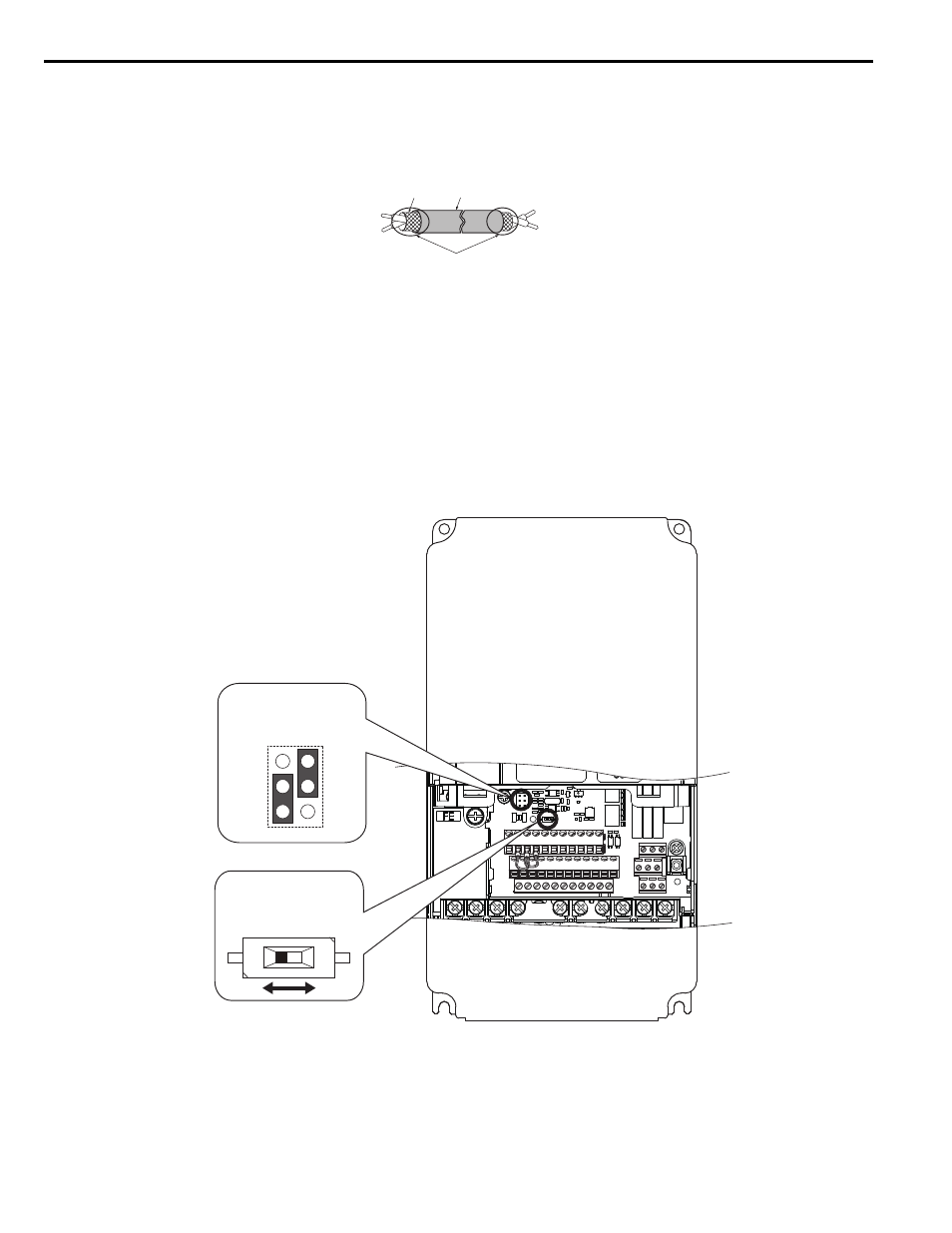
Switches and Jumpers on the Terminal Board
The terminal board is equipped with several switches used to adapt the drive I/Os to the external control signals.
shows the location of these switches.
Figure 14
Figure 14 Locations of Jumpers and Switches on the Terminal Board
A – Drive side
D – Shield sheath (insulate with tape or heat-shrink tubing)
B – Insulation
E – Shield
C – Control device side
A
E
B
C
D
Off
On
Jumper S3
Terminal H1/H2
Sink/Source Sel.
DIP Switch S2
RS-422/485 Termination
Resistor