Safe disable precautions, Using the safe disable function, 9 standards compliance – Yaskawa AC Drive-L1000E Safety Precautions User Manual
Page 46
9 Standards Compliance
46
YASKAWA TOEP YAIL1E 02A YASKAWA AC Drive - L1000E Safety Precautions
Safe Disable Precautions
DANGER! Sudden Movement Hazard. Improper use of the Safe Disable function will result in serious injury or death. Make sure the
entire system or machinery uses the Safe Disable function in compliance with safety requirements. When implementing the Safe
Disable function into the safety system of a machine, a thorough risk assessment for the whole system must be carried out to ensure it
complies with relevant safety norms (e.g., EN954/ISO13849, IEC61508, EN/IEC62061).
DANGER! Sudden Movement Hazard. When using a PM motor, even if the drive output is shut off by the Safe Disable function, a
break down of two output transistors can cause current to flow through the motor winding, resulting in a rotor movement for a maximum
angle of 180 degrees (electrically). Ensure this condition will not affect the safety of the application when using the Safe Disable
function. Failure to comply will result in death or serious injury.
DANGER! Electrical Shock Hazard. The Safe Disable function can switch off the drive output, but does not cut the drive power supply
and cannot electrically isolate the drive output from the input. Always shut off the drive power supply when performing maintenance or
installations on the drive input side as well as the drive output side. Failure to comply will result in death or serious injury.
DANGER! Sudden Movement Hazard. When using the Safe Disable inputs, make sure to remove the wire links between terminals H1,
H2, and HC that were installed prior to shipment. Failing to do so will keep the Safe Disable circuit from operating properly and can
cause injury or even death.
WARNING! All safety features (including Safe Disable) should be inspected daily and periodically. If the system is not operating
normally, there is a risk of serious personal injury.
WARNING! Only a qualified technician with a thorough understanding of the drive, the instruction manual, and safety standards should
be permitted to wire, inspect, and maintain the Safe Disable input. Failure to comply may result in serious injury or death.
NOTICE: From the moment terminal inputs H1 and H2 have opened, it takes up to 1 ms for drive output to shut off completely. The
sequence set up to trigger terminals H1 and H2 should make sure that both terminals remain open for at least 1 ms in order to properly
interrupt drive output. This may result in the Safe Disable Input not activating.
NOTICE: The Safe Disable Monitor (output terminals DM+ and DM–) should not be used for any other purpose than to monitor the
Safe Disable status or to discover a malfunction in the Safe Disable inputs. The monitor output is not considered a safe output.
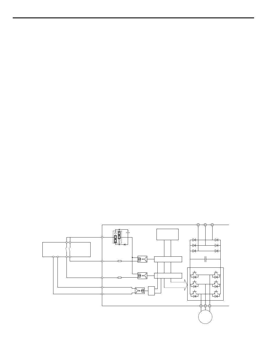
Using the Safe Disable Function
Safe Disable Circuit
The Safe Disable circuit consists of two independent input channels that can block the output transistors (terminals H1
and H2). The input can either use the drive internal power supply or an external power supply. Use jumper S3 on the
terminal board to select between Sink or Source mode with either internal or external power supply.
A photocoupler output is available to monitor the status of the Safe Disable terminals.
Refer to Output Terminals on
page 42
for signal specifications when using this output.
Additionally a Safe Disable monitor function can be assigned to one of the digital outputs (H2- = 58).
Figure 22
Figure 22 Safe Disable Function Wiring Example (Source Mode)
Safety
Outputs
Power Module P
N
M
Gate Block 2
Gate Block 1
Control
Circuit
Main Power
H1
H2
HC
Drive
Jumper S3
Setting:
SOURCE
>=1
DM+
DM-
Feedback
Safety Relay or PLC
with safety functionality
24 Vdc