8 troubleshooting, Troubleshooting, 8troubleshooting – Yaskawa AC Drive-L1000E Safety Precautions User Manual
Page 36
36
YASKAWA TOEP YAIL1E 02A YASKAWA AC Drive - L1000E Safety Precautions
8 Troubleshooting
8
Troubleshooting
Causes and Possible Solutions for Faults and Alarms
Alarm Codes
Alarms are drive protection functions that do not necessarily cause the drive to stop. Once the cause of an alarm is
removed, the drive will return to the same status as before the alarm occurred.
If a multi-function output is set for an alarm (H2- = 10), that output terminal will be triggered for certain alarms.
Note: If a multi-function output is set to close when an alarm occurs (H2- = 10), it will also close when maintenance periods are
reached, triggering alarms LT-1 through LT-4 (triggered only if H2- = 2F).
Fault Codes
Faults are detected for drive protection, and cause the drive to stop while triggering the fault output terminal MA-MB-
MC. Remove the cause of the fault and manually clear the fault before attempting to run the drive again.
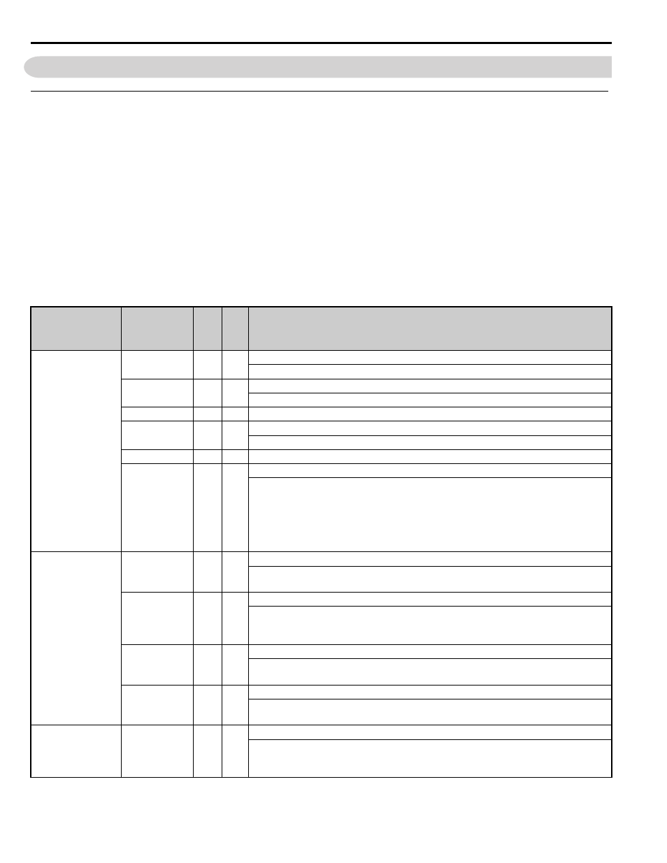
Table 16 JVOP-184 Alarm and Fault Codes, Indicators and Possible Solutions
JVOP-184
Status Text
ALARM
FAULT
Fault/Alarm
ALM FLT
Fault Name/Cause
ALARM(RUN)
AEr
O
Communication Option Node ID Setting Error (CANopen)
Option card node address is outside the acceptable setting range.
CALL
O
Serial Communication Stand By
Communication has not yet been established.
CrST
O
Cannot Reset
HCA
O
High Current Alarm
Drive current exceeded overcurrent warning level (133% of the rated current).
PASS
O
MEMOBUS/Modbus Communication Test Mode Complete
Uv
O
Undervoltage
One of the following conditions was true when the drive was stopped and a Up/Down
command was entered:
• DC bus voltage dropped below the level specified in L2-05.
• Contactor to suppress inrush current in the drive was opened.
• Low voltage in the control drive input power. This alarm outputs only if L2-01 is not 0
and DC bus voltage is under L2-05.
PGOH,LT
LT-1
O
Cooling Fan Maintenance Time
The cooling fan has reached its expected maintenance period and may need to be replaced.
Note: An alarm output (H2- = 10) will only be triggered if H2- = 2F.
LT-2
O
Capacitor Maintenance Time
The main circuit and control circuit capacitors are nearing the end of their expected
performance life.
Note: An alarm output (H2- = 10) will only be triggered if H2- = 2F.
LT-3
O
Soft Charge Bypass Relay Maintenance Time
The DC bus soft charge relay is nearing the end of its expected performance life.
Note: An alarm output (H2- = 10) will only be triggered if H2- = 2F.
LT-4
O
IGBT Maintenance Time (90%)
IGBTs have reached 90% of their expected performance life.
Note: An alarm output (H2- = 10) will only be triggered if H2- = 2F.
PGOH,LT
TrPC
O
IGBT Maintenance Time (90%)
IGBTs have reached 90% of their expected performance life.
Note: This alarm will not trigger a multi-function output terminal that is set for alarm
output (H2- = 10).