Default data example – Yaskawa MP900 Series Machine Controller Programming Panel for Simple Operation User Manual
Page 105
Quick Reference
4.3.7 Servo Driver Alarm
4-20
4
Default Data Example
The present register values will be displayed for each register.
Based on the above, the following description explains default data on the Servo Driver
Alarm page.
1. The Servo Driver Alarm page will by default display the servo driver alarm code data on
each axis that has been set.
These axes represent all axes defined as controller configuration items.
Axis definition data will be created based on the settings in the Setup Wizard 4: Module
Configuration Window. Refer to 3.2.4 Module Information.
2. The register number of the servo driver alarm code for each axis will be determined as
described below.
• The I (IWxxxx) register will be set to word data.
• The register numbers of the servo driver alarm code for each axis will be the register
numbers of the alarm flag plus two words.
In the above case, the numbers will be assigned as described below.
• Axes of Motion Module number 01
IWC024, IWC064, and IWC0A4 (three axes)
• Axes of Motion Module number 02
IWC424, IWC464, and IWC4A4 (three axes)
3. The comment on the servo driver alarm code of each axis consists of a logical axis name
and axis servo alarm code.
As defined, the logical axis name will be A, B, C, etc.
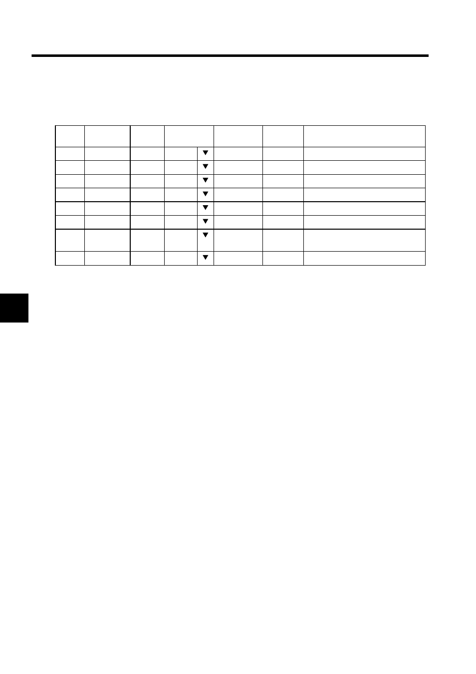
No.
Register
Number
DWG
Name
Display Type
Data
Symbol
Comment
1
IWC024
HEX
0000
A-axis servo alarm code
2
IWC064
HEX
0000
B-axis servo alarm code
3
IWC0A4
HEX
0000
C-axis servo alarm code
4
IWC424
HEX
0000
D-axis servo alarm code
5
IWC464
HEX
0000
E-axis servo alarm code
6
IWC4A4
HEX
0000
F-axis servo alarm code
.
.
60