5 axis definition, Number of axes, Window configuration – Yaskawa MP900 Series Machine Controller Programming Panel for Simple Operation User Manual
Page 83
3.2 Operation of Controller Configuration
3-13
3
3.2.5 Axis Definition
The Axis Definition Window displays physical axis names and logical axis names according
to the number of Servo Units set in Setup Wizard 4: Module Configuration Window.
Number of Axes
The following table shows the number of axes of each model.
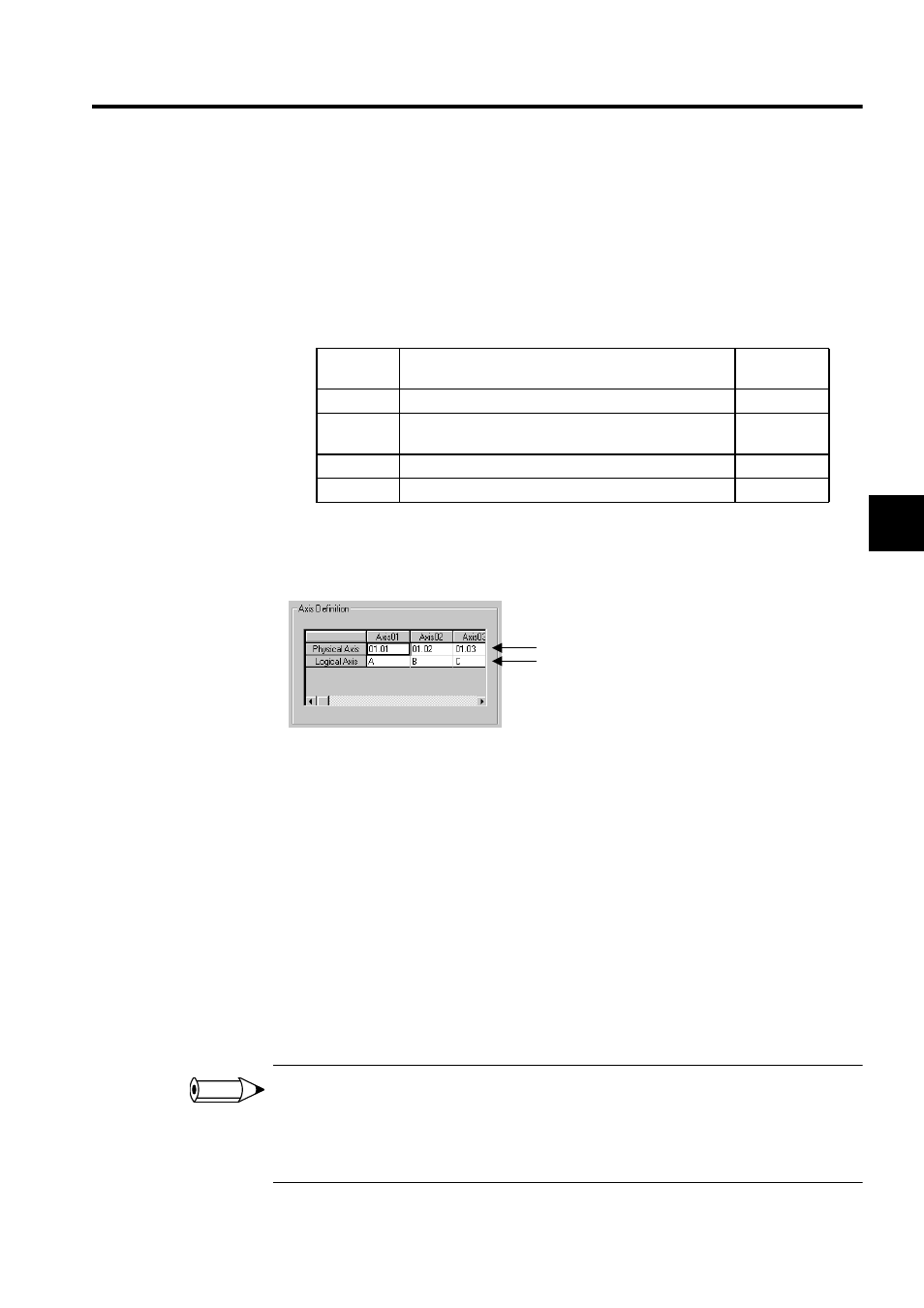
Window Configuration
The following illustration shows the window configuration.
1. Physical Axis Names
Motion module numbers and station numbers will be automatically allocated to the
physical axis names.
• Motion Module Numbers
These numbers apply to Motion Module numbers in the Definition Window in the
Engineering Manager.
• Station Numbers
Station numbers will be given to the above Modules, provided that the Modules are
Servos.
2. Logical Axis Names
Logical axis names will be assigned automatically in alphabetical order (e.g., A, B…Z,
AA, AB…ZZ).
1 Motion Module numbers will be allocated in order (e.g., 01, 02, and so on) to all Servo Modules set in
Setup Wizard 4: Module Configuration Window
.
2 Axis definition settings will be only displayed and cannot be changed. To change the settings, execute
the Setup Wizard again.
Model
Number of Axes
Range of
Axes
MP910
Number of SVB-CH1 and SVB-CH2 Servo Units
1 to 28
MP920
Number of SVA-01, SVA-02, and PO-01 axes in use and
number of SVB-01 Servo Units
1 to 48
MP930
Number of MP930 (SVB) Servo Units
1 to 14
MP940
Number of axes: Fixed at 1
-
1.
2.
INFO