Yaskawa MP900 Series Machine Controller Programming Panel for Simple Operation User Manual
Page 108
4.3 Default Data
4-23
4
2. The register numbers for each axis or each data item will be by default determined as
described below.
• The register numbers will be automatically set according to the number of Motion
Modules.
If two Motion Modules have been set, for example, the Servo with Motion Module
number 01 will be set to XXC0xx and the Servo with Motion Module number 02 will
be set to XXC4xx.
Refer to 3.2.4 Module Information for Motion Module numbers.
• The register numbers for each axis after the first axis will be assigned in 40-word
increments beginning with XXCx0x.
The register numbers will be XXC000, XXC040, and XXC080 if two Motion Mod-
ules have been set and three axes have been set for Motion Module number 01. The
numbers will be XXC400, XXC440, XXC480, and XXC4C0 if four axes have been
set for Motion Module number 02.
In the above description, “XX” refers to characters and “xx” refers to numerical values.
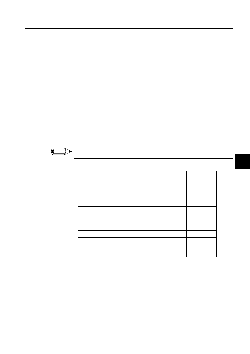
3. As shown below, the register and format of each data item and offset will be specified.
INFO
Data Name
Register
Data Type
Offset
Axis calculated position on
machine
I register
Long
2 words
Axis command position on
machine
I register
Long
18 words
Axis feedback position on machine
I register
Long
8 words
Axis position command pulse
setting
O register
Long
12 words
Axis motion command code
O register
Word
20 words
Axis motion command response
I register
Word
14 words
Axis alarm flag
I register
Long
22 words
Axis command busy
I register
Bit
15 words, 0 bit
Axis command completion
I register
Bit
15 words, 2 bits
Axis command error end status
I register
Bit
15 words, 7 bits