Yaskawa MPLoad Maker User Manual
Page 13
4 Creating Auto_MPLCD
4.2 Creating Auto_MPL
13
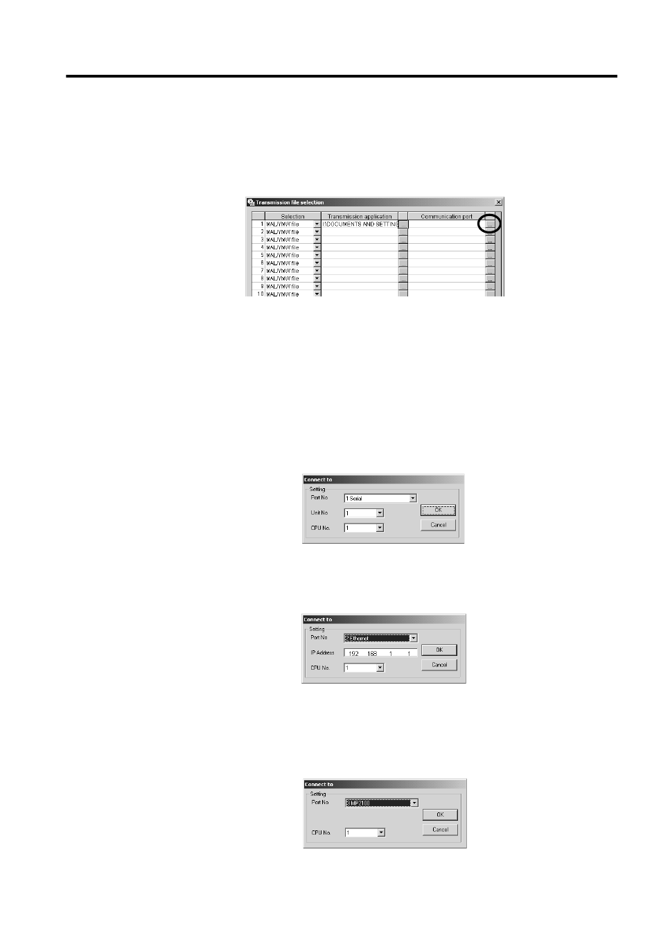
6.
Check the .mal or .ymw file path displayed in the Transmission application column, and then click
the button to the right of the Communication port column.
When the file path is too long to be displayed, drag the frame of the display field. A scroll bar will be displayed
on the bottom of the frame to scroll the display.
The Connect to Dialog Box will be displayed.
7.
Select the logical port number used for transfer in the Target PC from the Port No Box.
The items to be set will differ depending on the selected port type.
8.
Set the transfer destination Machine Controller (Module).
< When Serial is selected as Port No. >
Unit No.: The value set in the setting dialog box of the port type selected in the Communication setting Dialog
Box is displayed. It is possible to change the value.
CPU No: Select 1.
< When the 218 communication module is selected as Port No. >
IP Address: The default setting 192 168 1 1 is displayed. Change the setting to the IP address of the transfer
destination 218IF Module.
CPU No.: Select 1.
< When MP2100 is selected as Port No. >
CPU No.: Select the CPU number of the transfer destination Machine Controller. Select a CPU number from the
CP numbers (CPU numbers) in the setting dialog box of the MP2100 (port type) selected in the Communication
setting Dialog Box.
Selecting a CPU number other than those in the Communication setting Dialog Box will generate an alarm at
execution of transfer.