Yaskawa MPLoad Maker User Manual
Page 9
4 Creating Auto_MPLCD
4.1 Communications Settings for Target PC
9
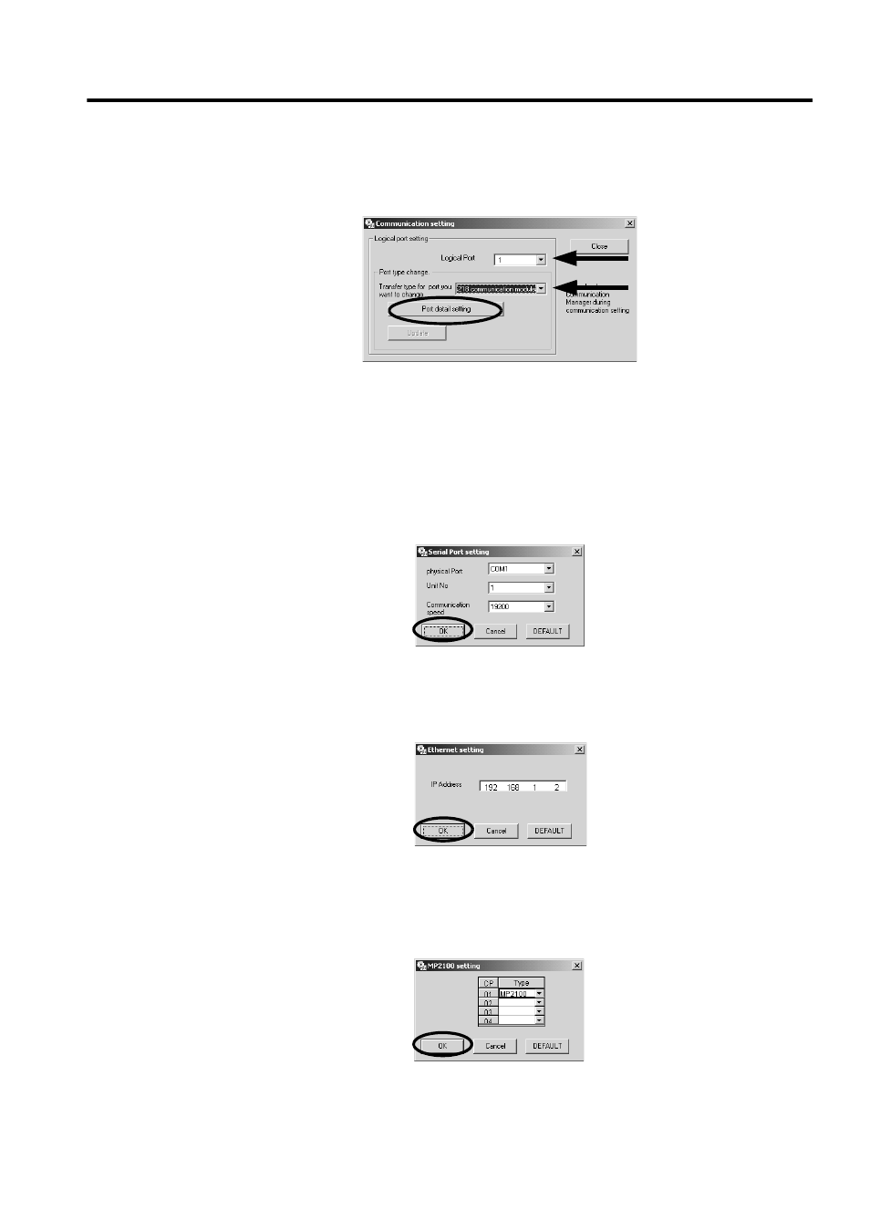
3.
Select the logical port number and port type (communications type) used for communications between
the Target PC and Machine Controllers, and then click the Port detail setting Button.
The setting dialog box for the selected port type will be displayed.
Selecting the port type will enable the Port detail setting Button.
When USB is selected as the port type, the Port detail setting Button will be invalid. Proceed to Step 5.
4.
Make the communications settings for the selected port.
<When Serial is selected as the port type>
The Serial Port setting Dialog Box will be displayed. Select the physical port, unit No., and commu-
nications speed, and then click the OK Button.
<When the 218 communication module is selected as the port type>
The Ethernet setting Dialog Box will be displayed. Type the IP address of the Target PC, and then
click the OK Button.
<When MP2100 is selected as the port type>
The MP2100 setting Dialog Box will be displayed. Click the arrow ▼ next to the CP number (set by
the dip switch of MP2100) of the transfer destination MP2100 board, select MP2100 from the Type
Box, and then click the OK Button.
The Communication setting Dialog Box will be displayed again and the Update Button will be enabled.