2 led indications – PLANET VC-2400MR48 User Manual
Page 19
User’s Manual of VC-820M / VC-2400MR Series
2.1.2 LED Indications
The front panel LEDs indicates instant status of port links, data activity and system power; helps monitor and troubleshoot
when needed.
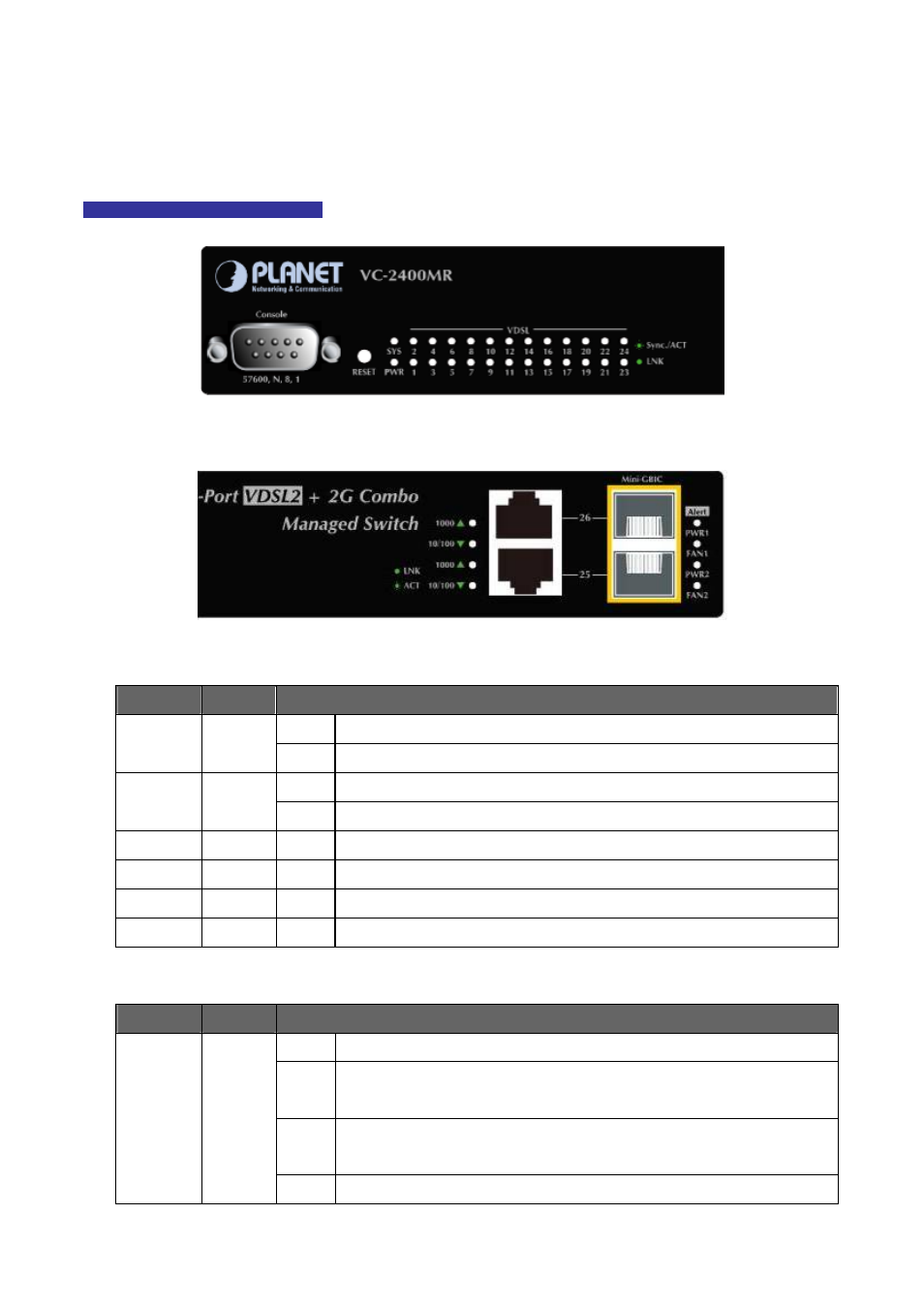
VC-2400MR Series LED indication
Figure 2-1-3:
VC-2400MR Series System and Port LED panel
Figure 2-1-4:
VC-2400MR Series Power and fan LED panel
■ System
LED
Color
Function
On:
Indicate that the Switch is powered on
PWR
Green
Off:
Indicate that the Switch is powered off
Lit:
Lights to indicate the system is working.
SYS
Orange
Blink Indicate that the system is in OS boot procedure or reset to default
PWR1
Orange
On:
Indicate that power1 is inserted and failed to work.
FAN1
Orange
On:
Indicate that fan1 is failed to work.
PWR2
Orange
On:
Indicate that power2 is inserted and failed to work.
FAN2
Orange
On:
Indicate that fan2 is failed to work.
■ Per VDSL Interface ( Port-1 to Port-24)
LED
Color
Function
On:
Indicate that the VDSL link is established.
Slow
Blink:
Indicate that the VDSL is at training status with remote CPE
Quick
Blink:
Indicate that the DATA link is actively sending or receiving data over that VDSL
port
VDSL
LNK/Sync
Green
Off:
Indicate that the VDSL is link down
19